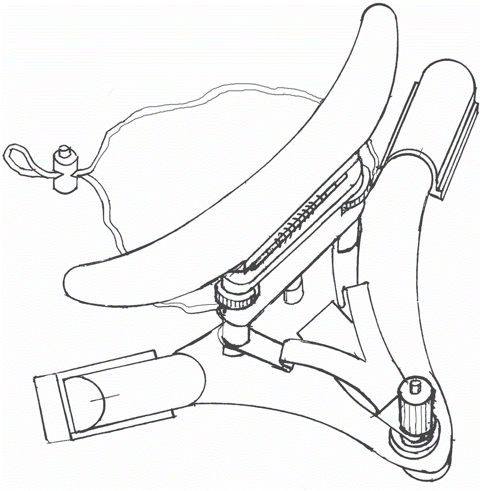
Magnetic levitation chin rest stop snoring device
A magnetic levitation and mandibular technology, applied in the field of medical devices, can solve the problems of high cost and recurrence rate, patient pain, unsatisfactory effect, etc., and achieve a good effect of stopping snoring
- Summary
- Abstract
- Description
- Claims
- Application Information
AI Technical Summary
Problems solved by technology
Method used
Image
Examples
Embodiment 1
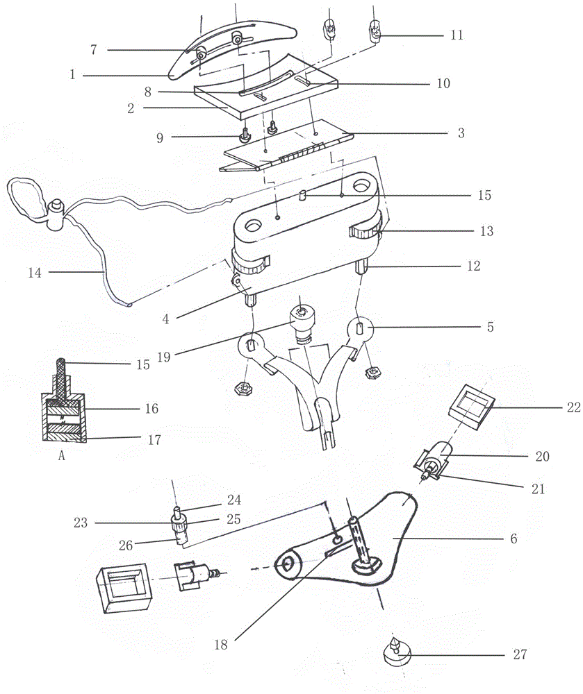
[0028] Such as figure 2 The magnetic suspension mandibular support snoring device includes: a mandibular bracket 1, a mandibular bracket slider frame 2, a tangential elastic bracket 3, a main working box 4, a multidirectional elastic bracket 5, and a main base 6.
[0029] The mandibular bracket 1 has a flat semicircular shape, and a horizontal sliding guide post 7 is provided on the lower surface. Slide rail groove 8 is provided on the lower jaw bracket slider frame. The lateral sliding guide post passes through the slide rail groove of the lower jaw bracket slider frame and is fixed by bolts 9. The lateral sliding guide post can slide in the slide rail groove to make the lower jaw The bracket can slide left and right on the lower jaw bracket slider frame.
[0030] The mandibular bracket slider frame is also provided with a T-shaped through slot 10, the upper part of which is placed a longitudinal adjusting pressure block 11 whose longitudinal size is smaller than the longitudina...
Embodiment 2
[0041] The mandibular bracket 1, the mandibular bracket slider frame 2, the tangential elastic bracket 3, the main body work box 4, the multidirectional elastic bracket 5, and the main base 6 of this embodiment are the same as those in the first embodiment.
[0042] The difference is that the top rod on the main working box pushes up the upper hinge of the tangential elastic support 3 through the electronic control device arranged inside the main working box.
[0043] The electronic control device includes a motor, a cam and an electronic control circuit. The electronic control circuit includes a contact switch, a delay circuit and a motor control circuit. The cam and the motor are fixedly connected, and the motor is sequentially connected to the motor control circuit, the delay circuit and the contact switch.
[0044] The contact switch includes a normally open contact and a normally closed contact. A second ejector rod that extends out of the main working box and passes through the ...
PUM
 Abstract
Description
Claims
Application Information
 - R&D
- Intellectual Property
- Life Sciences
- Materials
- Tech Scout
- Unparalleled Data Quality
- Higher Quality Content
- 60% Fewer Hallucinations
Browse by: Latest US Patents, China's latest patents, Technical Efficacy Thesaurus, Application Domain, Technology Topic, Popular Technical Reports.
© 2025 PatSnap. All rights reserved.Legal|Privacy policy|Modern Slavery Act Transparency Statement|Sitemap|About US| Contact US: help@patsnap.com


