LED display backplane groove dressing die

A technology for LED displays and backplanes, used in forming tools, manufacturing tools, metal processing equipment, etc., can solve problems such as poor product quality, loss of elasticity of elastic components, and inaccurate stamping products

Active Publication Date: 2015-04-01
JIANGSU FANRUN ELECTRONICS
View PDF7 Cites 1 Cited by
  • Summary
  • Abstract
  • Description
  • Claims
  • Application Information

AI Technical Summary

Problems solved by technology

Although the extrusion block uses a spring as the first elastic element to provide it with stable performance, the elastic element tends to lose

Method used


Image

  • LED display backplane groove dressing die
  • LED display backplane groove dressing die
  • LED display backplane groove dressing die

Examples


Example Embodiment

[0027] The preferred embodiments of the present invention will be described in detail below with reference to the accompanying drawings, so that the advantages and features of the present invention can be more easily understood by those skilled in the art, so as to make a clearer and clearer definition of the protection scope of the present invention.

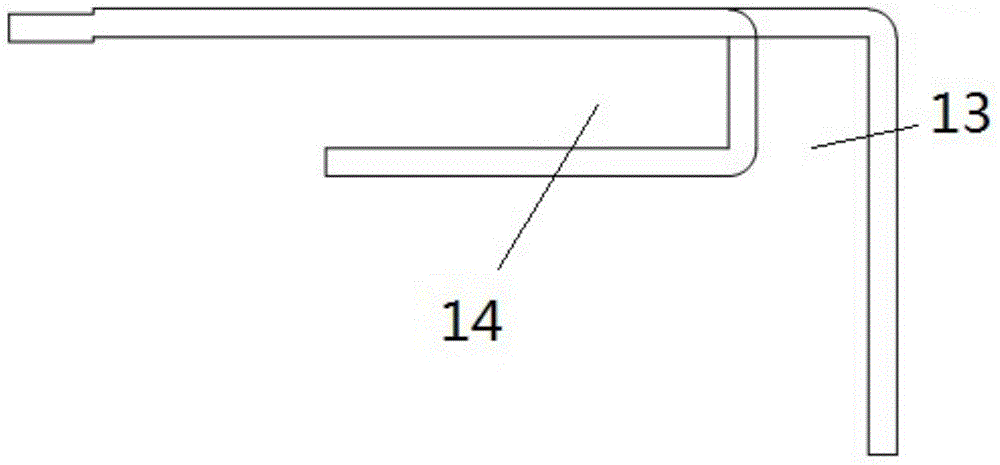
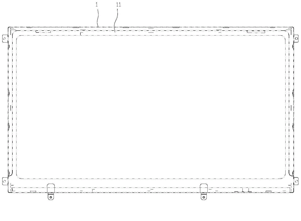
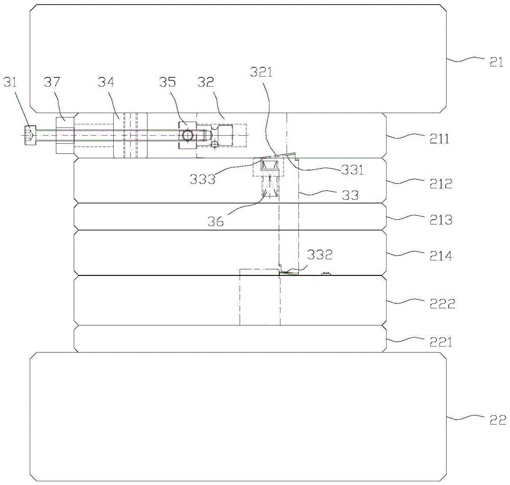
[0028] See attached Figure 1-8 As shown, the recess shaping mold for the LED display backplane in this embodiment is used to stamp and reshape the groove bending edge 11 of the LED display backplane 1. It includes an upper mold base 21 and an upper mold base 21. The shaping adjustment part 3, the shaping adjustment part 3 includes an adjustment screw 31, an inclined die 32, and an adjustment punch 33. The adjustment screw 31 is transversely arranged on the lower end surface of the upper die seat 21 through a screw fixing block 34, and the adjustment punch 33 and The adjusting screw 31 is vertical, the inclined die 32 is set at th...


PUM


Abstract

The invention discloses an LED display backplane groove dressing die. The LED display backplane groove dressing die comprises an upper die base (21) and a dressing adjusting part (3) arranged under the upper die base (21); the dressing adjusting part (3) comprises an adjusting lead screw (31), an oblique die (32) and an adjusting punch (33); the adjusting lead screw (31) is transversely arranged on the lower end face of the upper die base (21) by use of a lead screw fixed block (34); the adjusting punch (33) is perpendicular to the adjusting lead screw (31); the oblique die (32) is arranged at the end portion of the adjusting lead screw (31) by use of a ball roller (35); the left end of the ball roller (35) is fixedly connected with the end portion of the adjusting lead screw (31); the right end of the ball roller (35) is arranged in the oblique die (32) and capable of rotating relatively to the oblique die (32). The adjusting lead screw directly provides acting force to the oblique die in a linear manner and then the oblique die controls the adjusting punch to move; the LED display backplane groove dressing die has the advantages of stable force transfer and accurate oblique die motion.

Description

technical field [0001] The invention relates to the technical field of mold structures, in particular to a mold for shaping grooves on a backplane of an LED display. Background technique [0002] LED display (or LCD display) is a flat panel display device. In the structure of LED (or LCD display) display, the shell is tightly wrapped around the core LED (LCD) display components (PCB PANEL printed circuit board, SHEET reflective foil, etc. ) important parts. Since the LED (LCD) display panel itself does not emit light, it is necessary to install a lamp behind it to emit light, so the back panel not only plays the role of fixing the LED (LCD) display component, but also needs to provide reflection for the lamp installed in the groove. In order to improve the lighting effect of the lamp tube. It is generally used to fix the backplane of the LCD panel. It uses metal frame parts and connects the external shell. It can be said to be the "skeleton" of the LCD display. There are h...

Claims


Application Information

Patent Timeline
IPC IPC(8): B21D37/10B21D22/02
CPCB21D22/02B21D37/10
Inventor 朴日模彭春霞
Owner JIANGSU FANRUN ELECTRONICS
Why Eureka
Try Eureka