Automatic lubricating and cooling mechanism for stamping male dies

A technology of automatic lubrication and cooling mechanism, used in metal processing equipment, forming tools, manufacturing tools, etc., can solve problems such as increased labor costs, shortened mold life, increased lubrication, etc., to eliminate the degreasing process and labor, quality and mold. The effect of improving life and eliminating precision errors

Active Publication Date: 2015-04-01
SEKSUN TECH SUZHOU
View PDF7 Cites 1 Cited by
  • Summary
  • Abstract
  • Description
  • Claims
  • Application Information

AI Technical Summary

Problems solved by technology

[0002] Stamping punches in existing production such as figure 1 As shown, it is composed of fixed plate A 1, punch head A 2, unloading backing plate A 3, unloading plate A 4, belt material A 5, and concave plate A 6; there is no specific punch A 2 for stamping The automatic lubrication and cooling mechanism, the lubrication of the punch punch A 2 depends on manual work such as figure 1 Manually apply lubricated zone 7 as shown or apply lubricating oil to strip A 5 to increase lubrication and reduce temperature
[0003] Due to the failure to lubricate and cool down in time during production, the wear of the punch A 2 and the discharge plate A 4 is often increased, and the life of the die is shortened; at the same time, the die needs manual lubrication and maintenance after a certain period of production, and sometimes the die needs to be disassembled , the process is cumbersome; it is difficult to ensure the continuous production of the mold, which affects the efficiency; due to manual lubrication, the parts are stained with grease, and it is necessary to increase the degreasing process of the parts, which is not allowed for parts with special requirements; manual lubrication maintenance will cause Potential safety hazards and increased labor costs

Method used


Image

  • Automatic lubricating and cooling mechanism for stamping male dies
  • Automatic lubricating and cooling mechanism for stamping male dies
  • Automatic lubricating and cooling mechanism for stamping male dies

Examples


Embodiment Construction

[0020] The preferred embodiments of the present invention will be described in detail below in conjunction with the accompanying drawings, so that the advantages and features of the present invention can be more easily understood by those skilled in the art, so as to define the protection scope of the present invention more clearly.

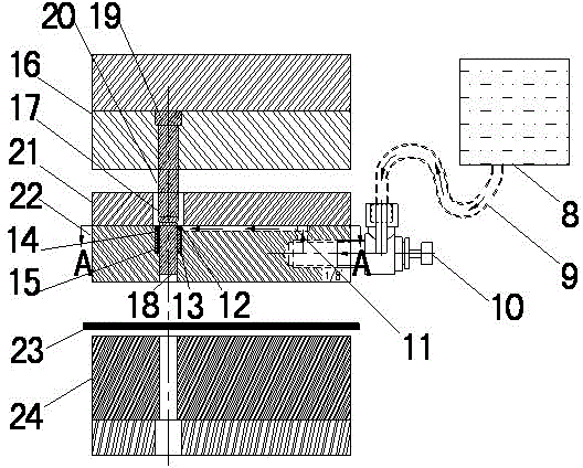
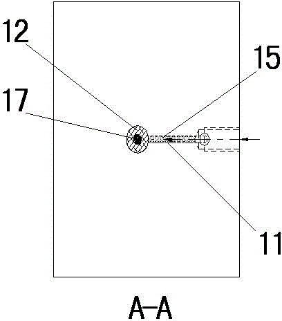
[0021] as attached figure 2 As shown in -3, an automatic lubrication and cooling mechanism for stamping punches according to the present invention includes: oil cup 8, oil pipe one 9, regulating valve 10, oil pipe two 11, oil seal one 12, oil seal two 13, storage Oil chamber 14, stamping oil 15; the position end of the oil outlet of the oil cup 8 is higher than the lower end of the fixed plate 16 or is flush with it and is connected with an oil pipe 9, and the other end of the oil pipe 9 is connected with one end of the regulating valve 10. The other end of the regulating valve 10 is connected with the oil pipe two 11, and the other end of the o...


PUM


Abstract

The invention discloses an automatic lubricating and cooling mechanism for stamping male dies. The automatic lubricating and cooling mechanism comprises an oil cup, wherein an oil outlet end of the oil cup is parallel and level to the lower end of a fixing plate and is connected with a first oil tube in parallel; the other end of the first oil tube is connected with one end of an adjusting valve; the other end of the adjusting valve is connected with a second oil tube; the other end of the second oil tube is communicated with an oil storage cavity; a first oil seal and a second oil seal are respectively arranged at two ends of the oil storage cavity; the oil storage cavity is formed in a discharging plate of a die; a punch penetrates in the oil storage cavity; the first oil seal and the second oil seal are arranged between a die head and a die shank of the punch; and the oil pressure between the oil cup and the oil storage cavity keeps balanced by adjusting the adjusting valve. When the punch moves in the up-down direction, a die rod positioned between the die head and the die shank are always soaked in stamping oil in the oil storage cavity partially, and the punch is always lubricated and cooled down by the stamping oil. By the automatic lubricating and cooling mechanism for the stamping male dies, the safety of workers, the efficiency and the quality of the stamping male dies are greatly improved, and the service lives of the stamping male dies are greatly prolonged.

Description

technical field [0001] The invention relates to an automatic lubricating and cooling mechanism for a stamping punch. Background technique [0002] Stamping punches in existing production such as figure 1 As shown, it is composed of fixed plate A 1, punch head A 2, unloading backing plate A 3, unloading plate A 4, strip material A 5, and concave plate A 6; there is no specific punch A 2 for stamping The automatic lubrication and cooling mechanism, the lubrication of the punch punch A 2 depends on manual work such as figure 1 Manually apply lubricating zone 7 as shown or apply lubricating oil on strip A 5 to increase lubrication and reduce temperature. [0003] Due to the failure to lubricate and cool down in time during production, the wear of the punch A 2 and the discharge plate A 4 is often increased, and the life of the die is shortened; at the same time, the die needs manual lubrication and maintenance after a certain period of production, and sometimes the die needs t...

Claims


Application Information

Patent Timeline
Patent Type & Authority Applications(China)
IPC IPC(8): B21D37/16B21D37/18
CPCB21D37/16B21D37/18
Inventor 顾英杰卞小军
Owner SEKSUN TECH SUZHOU
Why Eureka
Try Eureka