Closed-loop cycling type heat-dissipation apparatus

a heat dissipation apparatus and closed loop technology, applied in electrical devices, cooling/ventilation/heating modifications, racks/cabinets modified, etc., can solve the problems of heat dissipation, affecting the stability and operation life of the display, and unable to meet the need any more, so as to improve heat exchange efficiency and effectively lower the inner temperature

Inactive Publication Date: 2006-01-26
METAL INDS RES & DEV CENT
View PDF9 Cites 58 Cited by
  • Summary
  • Abstract
  • Description
  • Claims
  • Application Information

AI Technical Summary

Benefits of technology

[0010] It is another objective of the present invention to provide a closed-loop cycling type heat-dissipation apparatus, which utilizes a metal conduit to communicate with an upper hole and a lower hole of a housing to form a closed-loop cycling type heat-dissipation path around the housing. A plurality of heat-dissipation fins is disposed on an outer surface of the metal conduit to improve heat-exchange efficiency so as to effectively lower inner temperature of the housing and difference between inner temperature and outer temperature of the housing.

Problems solved by technology

It is a trend for electronic devices toward high density and high speed, which causes a problem of heat-dissipation.
However, when the heat is not dissipated on time, inner temperature of the display would rapidly rise, which largely and negatively affects display stability and operation life of the display.
Heat dissipation merely relied on the electronic device itself cannot satisfy the need any more.
The above two heat-dissipation implements merely dissipate local heat of the screen module, and cannot effectively lower heat from inner heat sources of the screen module.
Therefore, unbalance of inner temperature and outer temperature of the screen module cannot be resolved.
While the inner temperature of the screen module arising from the heat sources cannot be lowered due to lack of heat-dissipation apparatus for them.

Method used


Image

  • Closed-loop cycling type heat-dissipation apparatus
  • Closed-loop cycling type heat-dissipation apparatus
  • Closed-loop cycling type heat-dissipation apparatus

Examples


Embodiment Construction

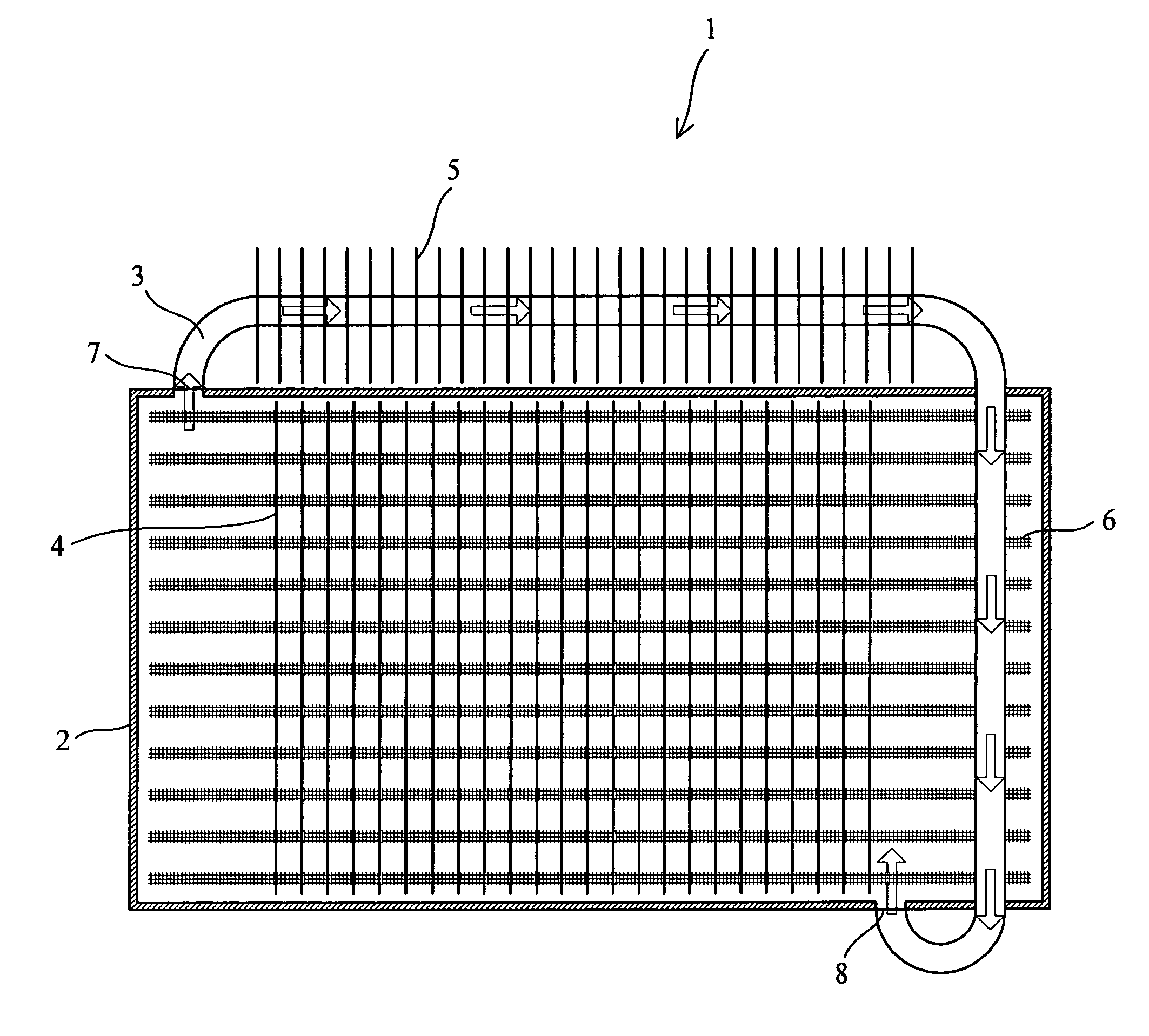
[0020] Firstly, referring to FIG. 1, which shows a schematic view of a structure of a screen module 1 according to one preferred embodiment of the present invention. In this preferred embodiment, a metal conduit 3 surrounds one side of a housing 2, with one end of the metal conduit 3 communicating with an upper exit 7 of the housing 2 and the other end of the metal conduit 3 communicating with a lower entrance 8 of the housing 2. A plurality of heat-dissipation fins 4 is arranged at a backside of the housing 2, and a plurality of heat-dissipation fins 5 is attached unto the metal conduit 3 and arranged in an equal-spaced manner along radial directions of the metal conduit 3.

[0021] Heat from the housing itself 2 is dissipated by the heat-dissipation fins 4 disposed at the backside of the housing 2, and hot air from the inner part of the housing 2 is channeled out through the metal conduit 3 communicating with the upper exit 7 of the housing 2. The hot air flows along an arrow direct...


PUM


Abstract

This invention provides a closed-loop cycling type heat-dissipation apparatus, including at least one metal conduit and plural heat-dissipation fins. Hot air in a housing of a screen module is channeled into the metal conduit through an upper exit of the housing. Heat-dissipation fins attached onto the metal conduit then make heat exchange with atmosphere. The heat of the hot air is dissipated to atmosphere by thermal convection or thermal radiation of surfaces of the heat-dissipation fins. The hot air is cooled down and then channeled into the housing of the screen module through a lower entrance thereof. A closed-loop heat-dissipation cycle is formed. Inner temperature of the housing and temperature difference between inner part and outer part of the housing are effectively lowered. The present apparatus can provide a capability sufficient for heat-dissipation while without the aid of other baggage. The heat-dissipation is relied on nature heat-dissipation cycle in a system and without thermal convection between air in the system and atmosphere.

Description

BACKGROUND OF THE INVENTION [0001] 1. Field of the Invention [0002] The present invention relates to a heat-dissipation apparatus, and more particularly to a closed-loop cycling type heat-dissipation apparatus, which can dissipate heat carried with hot air in a system by a nature heat-dissipation cycle. [0003] 2. Description of the Related Art [0004] As increasing advancement of IC (Integrated Circuit) technology, electronic industry is rapidly and persistently developed. It is a trend for electronic devices toward high density and high speed, which causes a problem of heat-dissipation. The demands of display quality, contrast, resolution and size of the display are persistently increased with integration density of display becoming higher and higher. Heat generated by the display is also increased. However, when the heat is not dissipated on time, inner temperature of the display would rapidly rise, which largely and negatively affects display stability and operation life of the di...

Claims


Application Information

Patent Timeline
Patent Type & Authority Applications(United States)
IPC IPC(8): H05K7/20
CPCH05K7/206
Inventor LAI, CHYI-LANGHUANG, TSUNG-WEN
Owner METAL INDS RES & DEV CENT
Why Eureka
Try Eureka