Control device, control method, and control program

a control device and control method technology, applied in the direction of domestic cooling devices, electric apparatus casings/cabinets/drawers, instruments, etc., can solve the problems of large amount of heat generated, and difficult to perform suitable temperature control when a non-operating server unit is presen

Active Publication Date: 2009-12-31
IBM CORP
View PDF7 Cites 60 Cited by
  • Summary
  • Abstract
  • Description
  • Claims
  • Application Information

AI Technical Summary

Benefits of technology

[0011]The present invention provides a control device, a control method, and a control program, capable of solving or obviating these and other deficiencies of the prior art.

Problems solved by technology

A server room of a data center has installed therein a number of server units, generating a large amount of heat.
When air-conditioning is used to control and maintain a constant temperature of the air drawn through the intake port of each of the server units, the following problems may occur if some server units are put into a non-operating state.
Accordingly, it is impossible to perform a suitable temperature control.
However, according to the invention disclosed in Japanese Patent Application Laid-Open No. 2006-208000, it may be difficult to perform a suitable temperature control when a non-operating server unit is present.
According to the invention disclosed in Japanese Patent Application Laid-Open No. 9-298377, although it is possible to detect a failure of the heat exchanger, it may be difficult to perform a suitable temperature control when a non-operating server unit is present.
According to the invention disclosed in Japanese Patent Application Laid-Open No. 2002-032152, although it is able to detect an abnormality in the flow speed due to a failure or the like of an internal fan and to perform a shutdown process, it may be difficult to perform a suitable temperature control when a non-operating server unit is present.

Method used


Image

  • Control device, control method, and control program
  • Control device, control method, and control program
  • Control device, control method, and control program

Examples


Embodiment Construction

[0024]The present invention will be described with respect to an embodiment thereof. The embodiment described below, however, is not limiting of the invention set forth in the appended claims, and all combinations of features described in the description of the embodiment are not necessarily indispensable to the solution according to the present invention.

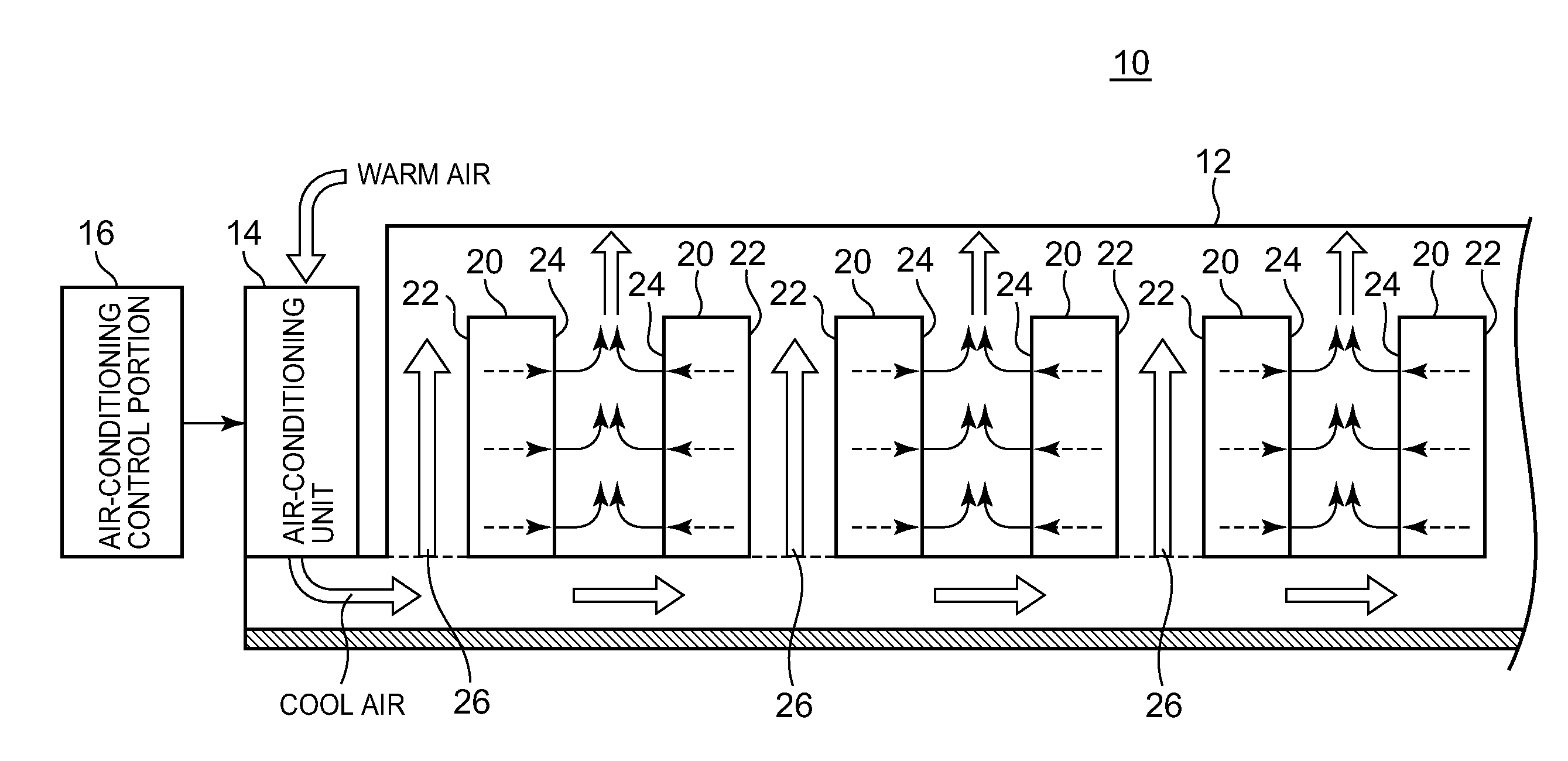
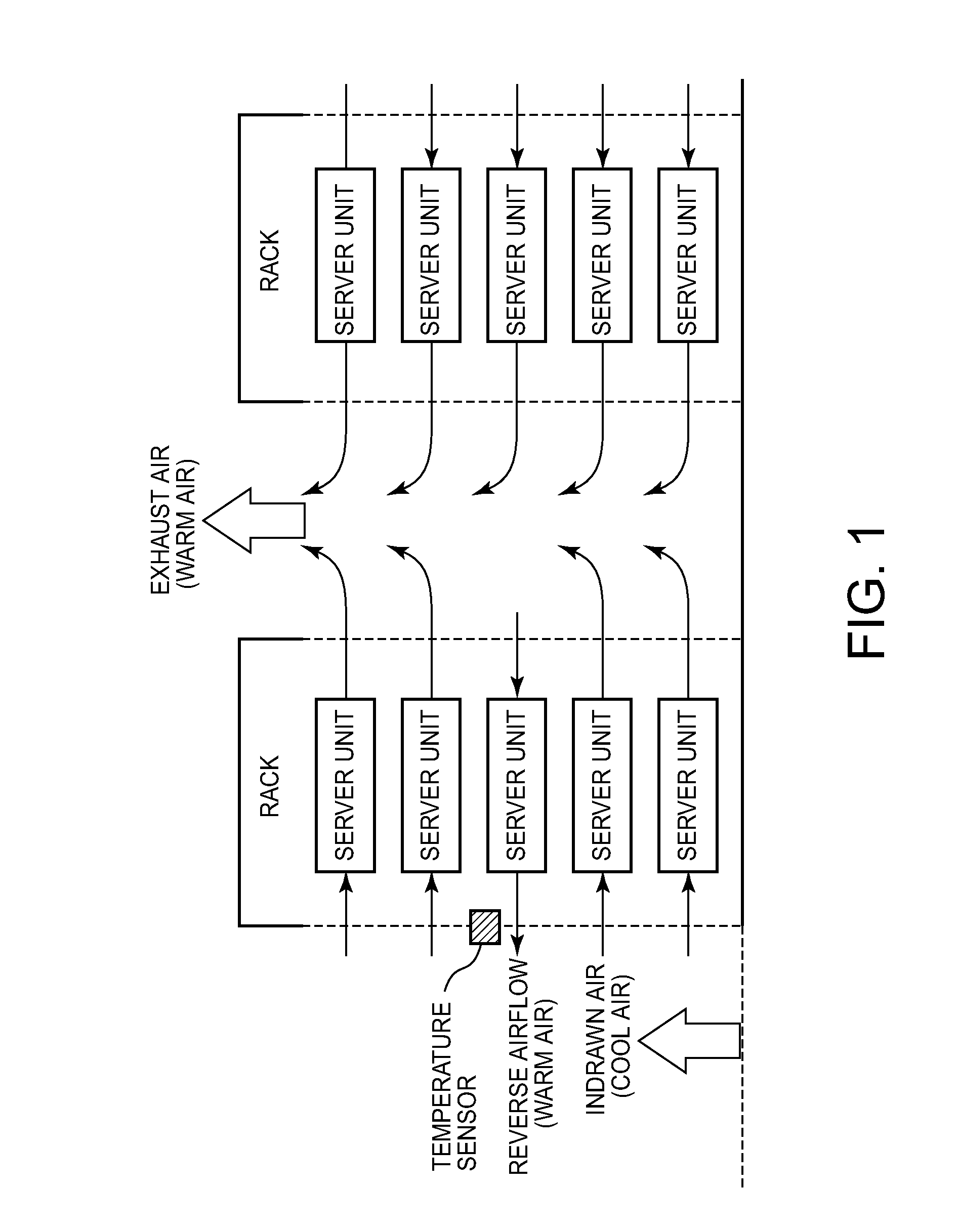
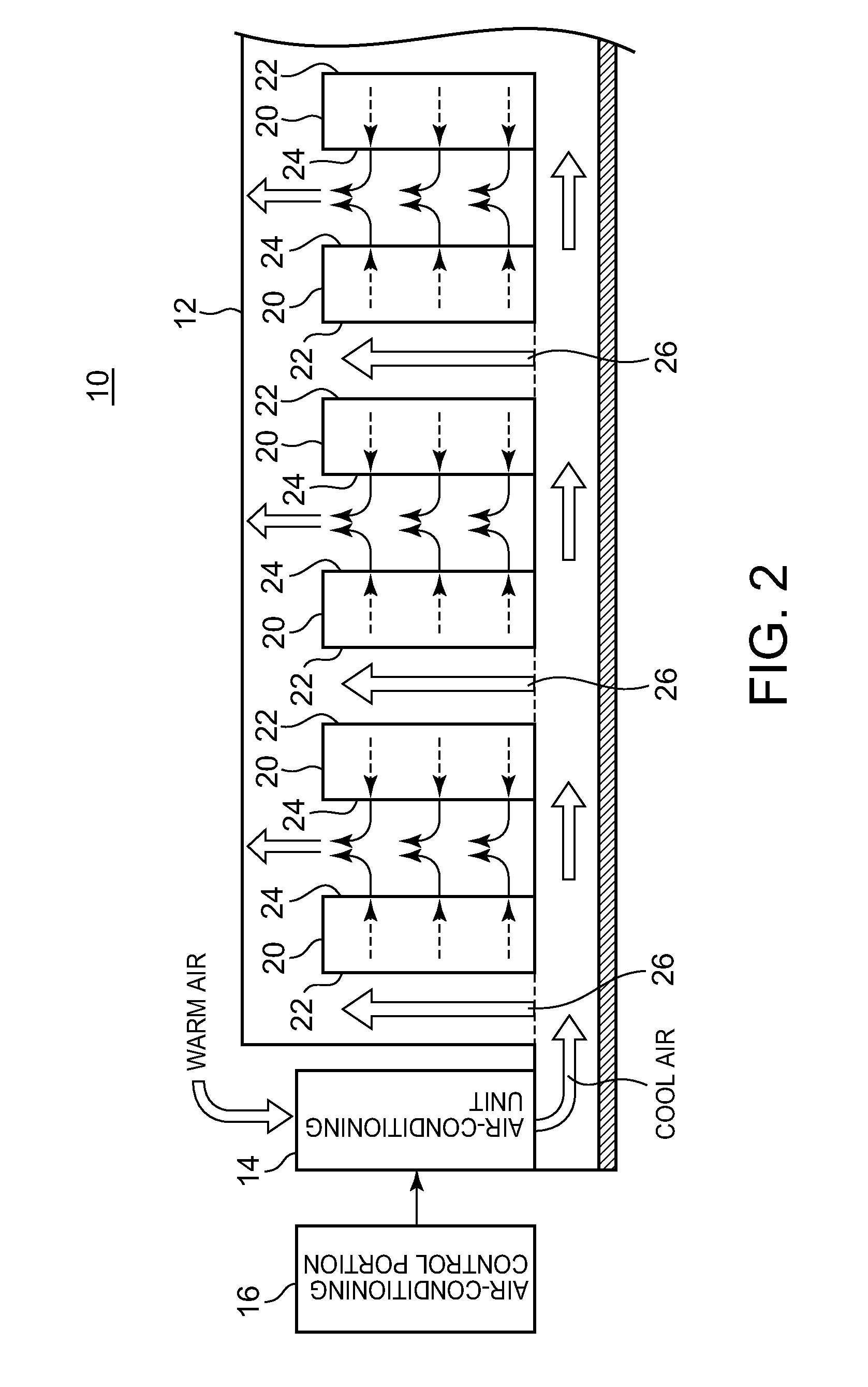
[0025]FIG. 2 is a diagram illustrating an exemplary construction of a data center 10 according to an embodiment of the present invention. FIG. 3 is a diagram illustrating an example of a plurality of pieces of equipment, in this case server units 30, mounted in a rack 20 and the flow of air around the rack 20.

[0026]The data center 10 is provided with a server room 12, an air-conditioning unit 14, and an air-conditioning control portion 16. In the server room 12, at least one rack 20 is provided. The air-conditioning unit 14 adjusts the air-conditioning of the interior of the server room 12. That is, the air-conditioning unit 14 sup...


PUM


Abstract

Provision of a control device, method and program capable of performing a suitable temperature control in a room having an equipment installed therein. A control device controls air-conditioning of a room having installed therein a plurality of pieces of equipment each being capable of drawing outside air to thereby cool down an interior of the equipment. A storage portion is capable of storing therein operating information that represents as to whether it is abnormal or not if each piece of equipment is put into a non-operating state. A temperature measurement portion is capable of measuring a temperature of the air drawn by each piece of equipment. A detection portion is capable of measuring a flow speed of the air drawn by each piece of equipment. A control portion is configured to control the air-conditioning based on the measurement result of the temperature or the flow speed of the air drawn by each piece of equipment.

Description

FIELD OF THE INVENTION [0001]The present invention generally relates to a control device, a control method, and a control program. More particularly, the present invention relates to a control device, a control method, and a control program capable of controlling air-conditioning of a room having equipment installed therein.BACKGROUND OF THE INVENTION [0002]A server room of a data center has installed therein a number of server units, generating a large amount of heat. Therefore, it is necessary to efficiently control air-conditioning of the server room of the data center to control the temperature.[0003]In the past, in a server room, an air-conditioning control wherein a temperature of a cool air supply (or blowing out) port of an air-conditioning unit is controlled to be constant, an air-conditioning control wherein a temperature of a warm air return port of the air-conditioning unit is controlled to be constant, or an air-conditioning control wherein a temperature of a wall surfa...

Claims


Application Information

Patent Timeline
Patent Type & Authority Applications(United States)
IPC IPC(8): G05D7/00G05D23/00H05K5/02
CPCF24F11/0001H05K7/20836H05K7/20745
Inventor SUGIYAMA, KENTAROHNAKAMURA, SATORU
Owner IBM CORP
Why Eureka
Try Eureka