Electronic engine control device, vehicle equipped with electronic engine control device, and electronic engine control method

a technology of electronic engine control and control device, which is applied in the direction of electrical control, engine starters, exhaust treatment electric control, etc., can solve the problems of significant deterioration of exhaust catalyst and low fuel consumption rate, so as to prevent significant deterioration of exhaust catalyst and improve fuel consumption rate

Inactive Publication Date: 2005-12-01
TOYOTA JIDOSHA KK
View PDF3 Cites 59 Cited by
  • Summary
  • Abstract
  • Description
  • Claims
  • Application Information

AI Technical Summary

Benefits of technology

[0006] The object of the present invention is to provide an electronic engine control device and corresponding method that ensure a good balance between prevention of significant deterioratio

Problems solved by technology

An exhaust catalyst significantly deteriorates, when being exposed to the lean exhaust atmosphere at

Method used


Image

  • Electronic engine control device, vehicle equipped with electronic engine control device, and electronic engine control method
  • Electronic engine control device, vehicle equipped with electronic engine control device, and electronic engine control method
  • Electronic engine control device, vehicle equipped with electronic engine control device, and electronic engine control method

Examples


Embodiment Construction

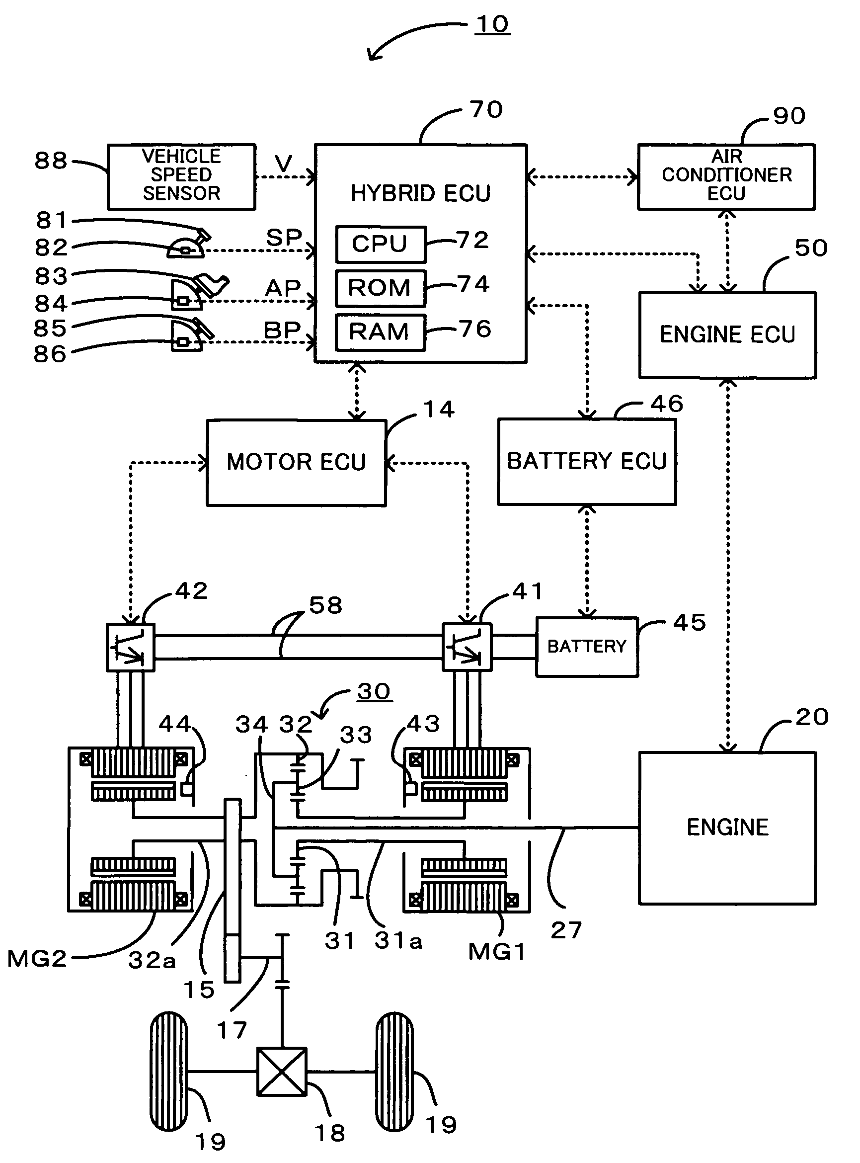
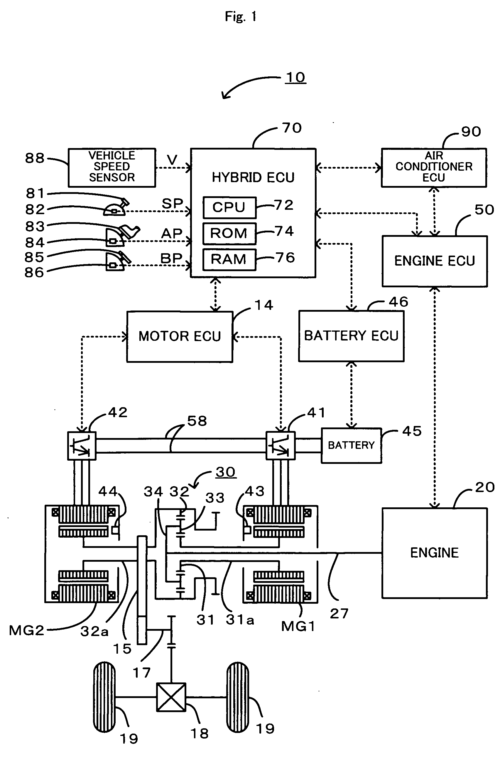
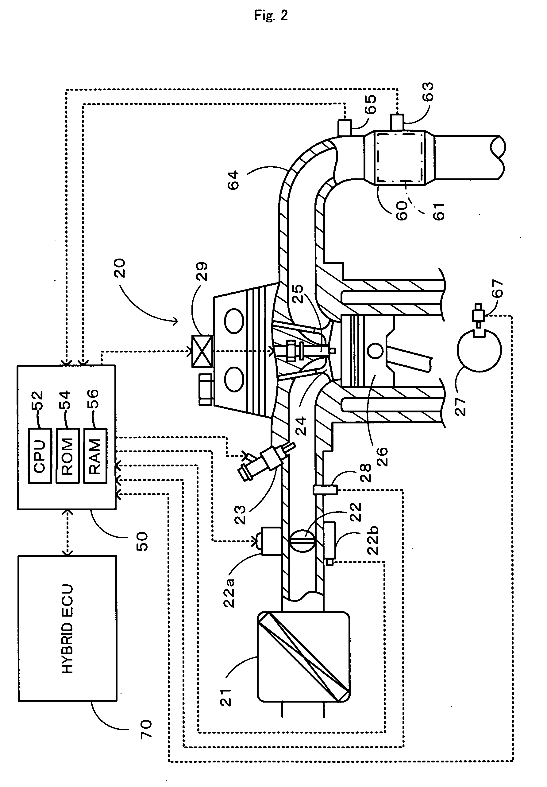
[0025]FIG. 1 schematically illustrates the configuration of a hybrid vehicle 10 in one embodiment of the invention. FIG. 2 schematically shows the structure of an engine 20 mounted on the hybrid vehicle 10 of the embodiment.

[0026] As illustrated in FIG. 1, the hybrid vehicle 10 includes the engine 20 that converts combustion energy generated by combustion of a fuel into kinetic energy, an engine electronic control unit (engine ECU) 50 that controls the whole engine system, a three shaft-type power distribution integration mechanism 30 that is linked to a crankshaft 27 or an output shaft of the engine 20, motors MG1 and MG2 that are connected to the power distribution integration mechanism 30 and are capable of generating electric power, and a motor electronic control unit (motor ECU) 14 that controls power generation and actuation of the motors MG1 and MG2. The hybrid vehicle 10 also includes a battery 45 that transmits electric power to and from the motors MG1 and MG2, a battery e...


PUM


Abstract

On the premise that a target torque of an engine is equal to 0, that observed catalyst temperature is in a specified temperature range causing deterioration of the catalyst, and that the engine runs idle without a fuel cut regardless of fulfillment of preset fuel cut conditions, the control procedure of the invention determines whether a predetermined engine stop condition is fulfilled (step S300). Upon fulfillment of the predetermined engine stop condition, the control procedure subsequently determines whether a high load is applied to an exhaust catalyst (step S320). The engine runs idle (step S310) when a high load is applied to the exhaust catalyst. The relatively low-temperature exhaust gas from the engine in the idling state forcibly cools down the exhaust catalyst. This prevents the exhaust catalyst from being kept at high temperature. When a low load is applied to the exhaust catalyst at step S320, on the other hand, the engine is stopped (step S330). The stop of the engine cuts off the air flow through the exhaust catalyst. The exhaust catalyst is thus not exposed to the lean exhaust atmosphere and does not significantly deteriorate even at high temperature.

Description

BACKGROUND OF THE INVENTION [0001] 1. Field of the Invention [0002] The present invention relates to an electronic engine control device and a vehicle equipped with the electronic engine control device, as well as a corresponding electronic engine control method. [0003] 2. Description of the Prior Art [0004] A known vehicle control device temporarily stops fuel injection to improve the fuel consumption rate, when a throttle valve is in full closed position and the engine rotation speed is not lower than a preset level (for example, when the vehicle runs down a slope without the driver's depression of an accelerator pedal). Rotation of the engine under the fuel cut keeps the air flow through the engine and thereby makes the lean exhaust atmosphere. An exhaust catalyst significantly deteriorates, when being exposed to the lean exhaust atmosphere at high temperature. One proposed technique disclosed in Japanese Patent Laid-Open Gazette No. 10-196433 prohibits the fuel cut when either a...

Claims


Application Information

Patent Timeline
IPC IPC(8): B60K1/02B60K6/445B60W20/00B60K6/448B60K6/52B60L50/16B60W10/06B60W10/08F01N3/00F01N3/20F01N11/00F02D17/00F02D29/02F02D41/02F02D41/04F02D41/12F02D41/14F02D41/22F02D45/00F02N11/08
CPCB60K1/02Y02T10/6239B60K6/445B60L2240/445B60W10/06B60W10/08B60W20/00B60W2510/0628B60W2510/068B60W2710/0616F01N11/002F02D41/0235F02D41/12F02D41/1495F02D41/221F02D2200/0802F02D2200/1002F02N11/0829Y02T10/54Y02T10/6286Y02T10/48B60K6/365Y02T10/40Y02T10/62
Inventor ICHIMOTO, KAZUHIROHARADA, OSAMU
Owner TOYOTA JIDOSHA KK
Why Eureka
Try Eureka