
Multi-workpiece drilling equipment with movable fixture

A drilling equipment, multi-workpiece technology, applied in drilling/drilling equipment, metal processing equipment, boring/drilling, etc. The hole process is reliable and accurate, the sliding distance is accurate, and the effect of avoiding the replacement of the workpiece

Inactive Publication Date: 2015-04-01
CHENGDU FANXINJIA TECH
View PDF6 Cites 17 Cited by
  • Summary
  • Abstract
  • Description
  • Claims
  • Application Information

AI Technical Summary

Problems solved by technology

[0002] At present, in the manufacturing process of rotary joints and other parts, the end face hole processing of disc parts is usually completed by drilling equipment. The fixture on the existing drilling equipment cannot self-lock after clamping, and the workpiece is easy to loose when the force is large. Moreover, most of them are single-piece clamping. In batch processing, the number of loading and unloading is too many and the operation is troublesome, which cannot meet the needs of multiple clamping, resulting in low processing efficiency, and the cumulative error caused by multiple clampings affects the processing quality of workpieces.

Method used


Image

  • Multi-workpiece drilling equipment with movable fixture
  • Multi-workpiece drilling equipment with movable fixture

Examples


Embodiment Construction

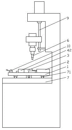
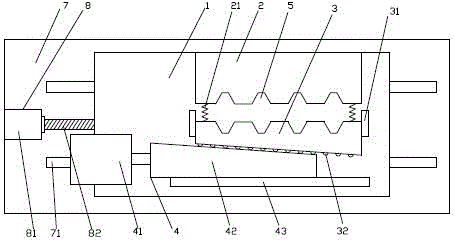
[0010] The present invention will be described in further detail below through specific implementation examples and in conjunction with the accompanying drawings.

[0011] figure 1 , figure 2 Shown is the clamp displacement type multi-workpiece drilling equipment provided by the present invention, including a frame and clamps positioned on the frame, a drill bit 6 is arranged above the corresponding clamps on the frame; The slide table 7 of rail 71, fixture is fixed on the slide rail 71; Fixture is connected with the fixture driving device 8 that drives it to slide, and fixture driving device 8 comprises motor 81, the lead screw 82 that is connected with motor 81, the screw on the lead screw 82 The rod nut and the lead screw nut are connected with the fixture; the fixture includes a fixture bottom plate 1, a positioning block 2 and a clamping block 3 located on the fixture bottom plate 1 and oppositely arranged, and a clamping block drive that drives the clamping block 3 to ...


PUM


Abstract

The invention discloses multi-workpiece drilling equipment with a movable fixture, and belongs to the technical field of machining equipment. The multi-workpiece drilling equipment comprises a framework and the fixture. The fixture is positioned on the framework; a drill bit is arranged on the upper side of the framework and corresponds to the fixture; a slide table is further arranged on the framework, and slide rails are arranged on the surface of the slide table; the fixture comprises a fixture bottom plate, a positioning block, a clamping block and a clamping block driving device, the positioning block and the clamping block are positioned on the fixture bottom plate and are opposite to each other, and the clamping block driving device can drive the clamping block to slide towards the positioning block; a return spring is arranged between the positioning block and the clamping block in a connected manner; V-shaped grooves which correspond to one another are formed in opposite surfaces of the positioning block and the clamping block; the clamping block driving device comprises a cylinder and a wedge block, the wedge block is connected with a piston rod of the cylinder, and an oblique plane is arranged on the surface, which is opposite to the corresponding V-shaped grooves, of the clamping block and is matched with an oblique plane of the wedge block; rollers are arranged and supported on the oblique plane of the clamping block, and the oblique plane of the wedge block is tangential to the surfaces of the rollers. The multi-workpiece drilling equipment has the advantages that the machining efficiency can be improved, self-locking effects can be realized after workpieces are clamped, the multi-workpiece drilling equipment can be automatically reset after the workpieces are completely machined, and drilling procedures can be reliably and accurately carried out.

Description

technical field [0001] The invention relates to the technical field of mechanical processing equipment, in particular to a clamp-shifting multi-workpiece drilling equipment. Background technique [0002] At present, in the manufacturing process of rotary joints and other parts, the end face hole processing of disc parts is usually completed by drilling equipment. The fixture on the existing drilling equipment cannot self-lock after clamping, and the workpiece is easy to loose when the force is large. Moreover, most of them are single-piece clamping. In batch processing, the number of loading and unloading is too many and the operation is troublesome, which cannot meet the needs of multiple clamping, resulting in low processing efficiency, and the cumulative error caused by multiple clampings affects the processing quality of workpieces. Contents of the invention [0003] The object of the present invention is to provide an efficient multi-workpiece fixture shifting multi-w...

Claims


Application Information

Patent Timeline
Patent Type & Authority Applications(China)
IPC IPC(8): B23B41/00B23Q3/08B23Q7/00
CPCB23B41/00B23Q3/061B23Q3/08B23Q7/00B23Q2703/04
Inventor 高静袁代华邓金智
Owner CHENGDU FANXINJIA TECH
Learn More