Extrusion type steel pipe cutter and fabrication method thereof

A production method and extrusion technology, which is applied to pipe shearing devices, manufacturing tools, knives for shearing machine devices, etc., can solve the problems of unusable cutting knives, explosion of pipes, and inability to cut steel pipes, etc.

Inactive Publication Date: 2015-04-01
陈晨
View PDF8 Cites 1 Cited by
  • Summary
  • Abstract
  • Description
  • Claims
  • Application Information

AI Technical Summary

Problems solved by technology

Under the existing technical conditions, electric cutting and acetylene gas cutting can be used to cut it. However, if it is used as a pipeline for transporting some chemical raw materials, it is not suitable to use electric cutting and acetylene gas cutting. High temperature is generated in the medium, which is easy to cause the pipeline to explode
However, the structure of the traditional cutting knife is usually long in one direction. If the steel pipe to be cut is at the corner and the outer wall of the steel pipe is close to the wall, the traditional cutting knife will be limited by the location and environment of the steel pipe to be cut and cannot be used.
The patent number is: 2014202300928, which involves a device for extruding and cutting steel pipes. Due to the fact that the length of the rocker arm of the device is too long due to the fact that the cutting rocker arm is fixed on the device, it is also impossible to cut steel pipes whose outer wall is closer to the wall.

Method used


Image

  • Extrusion type steel pipe cutter and fabrication method thereof
  • Extrusion type steel pipe cutter and fabrication method thereof

Examples


Embodiment Construction

[0014] The present invention will be further described in detail below in conjunction with the accompanying drawings, but not as any limitation to the present invention.

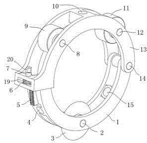
[0015] Embodiment of the present invention: a manufacturing method of an extruded steel pipe cutter, the method adopts a circular cutter blade to be assembled on the lower tool holder through the blade shaft, the roller one is assembled on the upper tool holder through the roller shaft, and the roller two The roller shaft 2 is assembled on the upper knife rest, the extrusion wheel is assembled on the extrusion shaft, and the lower end surface of the extrusion wheel is attached to the bottom surface of the extrusion groove of the upper knife rest, and the extrusion shaft is assembled on the upper knife rest, and The upper teeth of the extrusion wheel mesh with the extrusion teeth on the lower tool holder, and the working end of the plunger is in clearance fit with the upper shelf socket of the upper tool holde...


PUM


Abstract

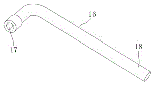
The invention discloses an extrusion type steel pipe cutter and a fabrication method thereof. According to the method, a circular cutter blade is assembled on a lower knife rest through a blade shaft; an idler wheel I is assembled on an upper knife rest through an idler wheel shaft I; an idler wheel II is assembled on the upper knife rest through an idler wheel shaft II; an extrusion wheel is assembled on an extrusion shaft; the lower end surface of the extrusion wheel is fitted to the bottom surface of an extrusion groove of the upper knife rest; the extrusion shaft is assembled on the upper knife rest; ridges on the extrusion wheel are engaged with extrusion teeth on the lower knife rest; the working end of an inserted link, an upper frame inserting hole of the upper knife rest and a lower frame inserting hole I and a lower frame inserting hole II of the lower knife rest are in clearance fit; the working end of the inserted link is inserted into the extrusion type steel pipe cutter when the extrusion type steel pipe cutter is used; an inner hexagon head of the inserted link is matched with an outer hexagon head on the extrusion shaft; rotation of the extrusion shaft is achieved by rotating the inserted link. According to the extrusion type steel pipe cutter, the circular cutter blade is inserted into the outer wall of a to-be-cut steel pipe in an extrusion manner, then a cutting groove is cut out from the outer wall of the steel pipe by virtue of the cutter blade and finally, the steel pipe is cut off.

Description

technical field [0001] The invention relates to an extruded steel pipe cutter and a manufacturing method, belonging to the technical field of steel pipe cutting equipment. Background technique [0002] In the construction process of some factory buildings and high-rise buildings, various steel pipes are commonly used to support heavy objects or lay them in the wall as conveying pipes. However, due to construction needs or other factors, the exposed part of the pipe fittings on the wall must be cut off. Under the existing technical conditions, electric cutting and acetylene gas cutting can be used to cut it. However, if it is used as a pipeline for transporting some chemical raw materials, it is not suitable to use electric cutting and acetylene gas cutting. The high temperature generated in the medium is easy to cause the pipeline to explode. However, the structure of the traditional cutter usually has a long length in one direction. If the steel pipe to be cut is at the co...

Claims


Application Information

Patent Timeline
IPC IPC(8): B23D21/04B23D21/10B23D35/00
Inventor 陈晨陈志俭陈辉
Owner 陈晨
Why Eureka
Try Eureka