Motor excitation coil insulating layer breaking device

A technology of motor excitation and insulating layer, applied in electromechanical devices, manufacturing motor generators, electrical components, etc., can solve the problems of inconvenience and complexity of motor manufacturers, avoid irregularities and inconsistencies, improve efficiency, and solve cumbersome processes. Effect

Pending Publication Date: 2020-07-14
苏州汇智卓安自动化科技有限公司
View PDF0 Cites 0 Cited by
  • Summary
  • Abstract
  • Description
  • Claims
  • Application Information

AI Technical Summary

Problems solved by technology

At present, the method for electric motor manufacturers to heat the coil is relatively complicated. It is necessary to remove the coil from the equipment and manually remove the insulation layer at t...

Method used


Image

  • Motor excitation coil insulating layer breaking device

Examples


Embodiment

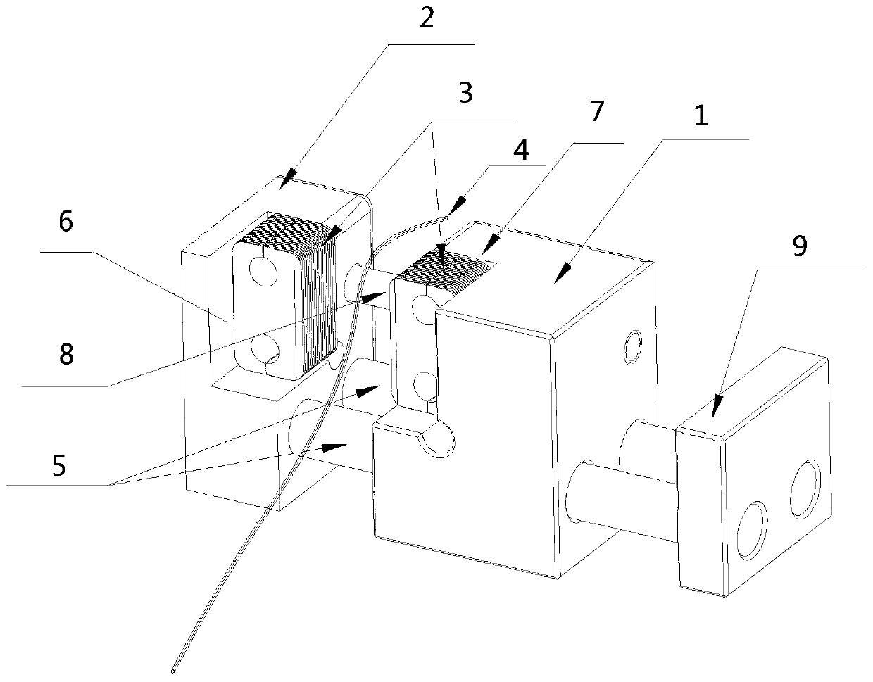
[0020] Such as figure 1 The shown device for breaking the insulating layer of a motor excitation coil includes a fixed clamp block 1, a movable clamp block 2, and extrusion teeth 3 respectively fixed on the opposite surfaces of the fixed clamp block 1 and the movable clamp block 2, and the extrusion teeth 3. Power on; specifically, during installation, the fixed clip 1 and the movable clip 2 are rectangular, which is convenient for installation and layout. At the same time, the fixed clip 1 is fixedly installed on the stator winding machine during installation. The movable clamping block 2 is movably set on the stator winding machine, and can move relative to the fixed clamping block 1, so as to ensure that the extrusion teeth on the corresponding surfaces of the fixed clamping block 1 and the movable clamping block 2 can be squeezed against each other. The insulation layer of the wire 4 between the fixed clamp block 1 and the movable clamp block 2 is crushed to facilitate ele...


PUM


Abstract

The invention relates to a motor excitation coil insulating layer breaking device. The device comprises a fixed clamping block, a movable clamping block and extrusion teeth which are fixedly arrangedon the opposite surfaces of the fixed clamping block and the movable clamping block respectively; the device further comprises a driving device; the driving device drives the fixed clamping block andthe movable clamping block to extrude each other, so that the insulating layer of a wire placed between the extrusion teeth on the fixed clamping block and the movable clamping block is crushed. The extrusion teeth are utilized, the wire is placed on the surfaces of the extrusion teeth, and the tips of the extrusion teeth are pressed to break the insulating layer of the wire by applying pressure to the extrusion teeth, so that a coil and a circuit are simply, conveniently and quickly connected to form a circuit loop, the tedious process of manual operation of workers is solved, production efficiency is greatly improved, and the defects of non-standardization and non-consistency of manual operation are avoided.

Description

technical field [0001] The invention relates to the technical field of motor production, in particular to a device for breaking an insulating layer of a motor excitation coil. Background technique [0002] Electric machines convert electrical power into mechanical torque by inducing a rotating magnetic field between a stationary element (ie, the stator) and a rotatable element (ie, the rotor) with field coils. Torque is transmitted to the shaft, which is coupled to the rotor by conductor bars. A field coil may be associated with the stator. [0003] At present, in the stator production process, it is a very important process to energize and heat the excitation coil (hereinafter referred to as "coil") to melt the skin glue and then bond to each other. Improving production efficiency and reducing labor intensity is also the key point that must be controlled in factory operations. At present, the method for electric motor manufacturers to heat the coil is relatively complicat...

Claims


Application Information

Patent Timeline
IPC IPC(8): H02K15/12H02K15/04H02K15/00
CPCH02K15/0068H02K15/04H02K15/12
Inventor 杜坤林巧民陈小乐李嘉关建飞肖辉李峻
Owner 苏州汇智卓安自动化科技有限公司
Why Eureka
Try Eureka