Special clamp of irregular workpieces

A technology for special fixtures and special-shaped workpieces, which is applied in the direction of manufacturing tools, metal processing machinery parts, clamping, etc., can solve the problems of heavy workload, cumbersome disassembly and assembly process, time-consuming and labor-intensive, and achieve the effect of improving efficiency

Inactive Publication Date: 2015-04-01
常州中远精密工具厂
View PDF0 Cites 4 Cited by
  • Summary
  • Abstract
  • Description
  • Claims
  • Application Information

AI Technical Summary

Problems solved by technology

[0002] When processing ring parts with steps, it is very cumbersome to use ordinary chucks or combined fixtures in the proce...

Method used


Image

  • Special clamp of irregular workpieces

Examples


Embodiment Construction

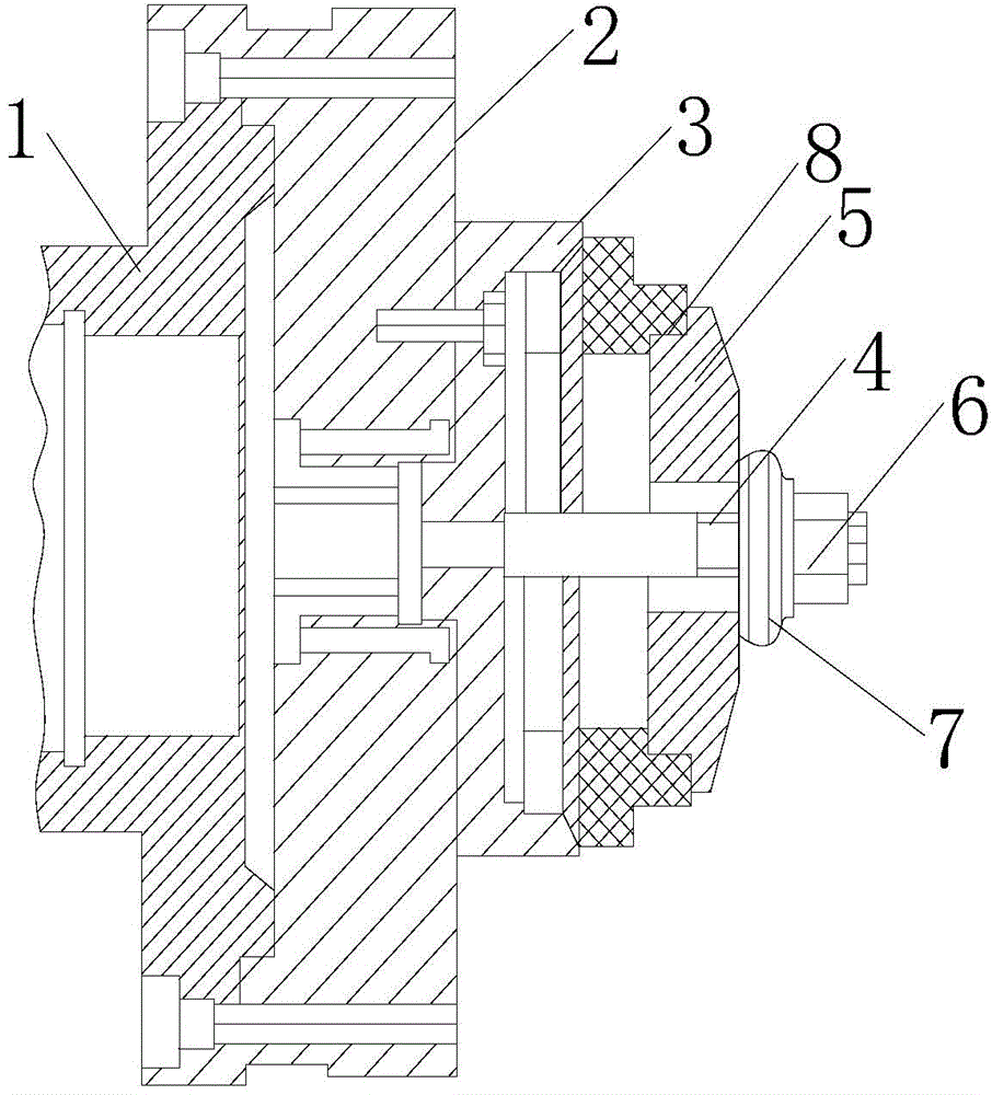
[0010] Such as figure 1 As shown, the special fixture for special-shaped workpieces includes, from left to right, an annular transition plate 1, an annular faceplate 2 connected with the transition plate 1, and a clamping device connected with the faceplate; the clamping device includes a sleeve at the left end The support sleeve 3 in the faceplate, the screw 4 that runs through the support sleeve, the pressure plate 5 that is sleeved on the screw 4, and the washer 7 and the nut 6 that are sleeved on the right end in turn; The compression step part 8.

[0011] When in use, because the screw is installed in the support sleeve, and the support sleeve is installed in the faceplate, the screw is fixed on the faceplate indirectly; and because the pressure plate set on the screw is provided with a compression step, the entire step surface of the workpiece is in line with the pressure plate. The tight step contact not only prevents the workpiece from moving axially, but also prevent...


PUM


Abstract

The invention relates to the technical field of machine tool clamps, in particular to a special clamp of irregular workpieces. The special clamp comprises a transition plate, a face plate connected with the transition plate, and a clamping device connected with the face plate. The clamping device comprises a supporting sleeve with the left end sleeved in the face plate, a screw penetrating through the supporting sleeve, a pressing plate sleeved on the screw, and a nut and a gasket which are used for fastening the pressing plate. A pressing step portion fit with the step surfaces of workpieces is arranged at the left end of the pressing plate. The special clamp facilitates processing of annular parts with steps.

Description

technical field [0001] The invention relates to the technical field of machine tool fixtures, in particular to special-shaped fixtures for workpieces. Background technique [0002] When processing ring parts with steps, it is very cumbersome to use ordinary chucks or combined fixtures in the process of alignment, clamping and centering, especially when there are many such workpieces, the workload is very huge ,Time-consuming. Contents of the invention [0003] The purpose of the present invention is to provide a special-shaped workpiece fixture which is convenient for processing the annular parts with steps. [0004] Technical scheme of the present invention is as follows: [0005] The special fixture for special-shaped workpieces includes, from left to right, a transition plate, a face plate connected with the transition plate, and a clamping device connected with the face plate; Screws, a pressing plate sleeved on the screws, and nuts and washers for fastening the pre...

Claims


Application Information

Patent Timeline
IPC IPC(8): B23Q3/00
CPCB23Q3/00B23Q2703/10
Inventor 言小琴
Owner 常州中远精密工具厂
Why Eureka
Try Eureka