Al technical title is built by PatSnap Al team. It summarizes the technical point description of the patent document.
A rotating structure and mechanical technology, applied in non-mechanical transmission-operated locks, building locks, lock applications, etc., can solve the problems such as the inconvenience of the lock cylinder switch lock, poor anti-theft effect, etc., and achieve easy and convenient locking and unlocking. , The effect of improving the appearance of the city and the prospect of use
Active Publication Date: 2015-04-01
考克(福建)工业设计有限公司
View PDF6 Cites 3 Cited by
Summary
Abstract
Description
Claims
Application Information
AI Technical Summary
This helps you quickly interpret patents by identifying the three key elements:
Problems solved by technology
Method used
Benefits of technology
Problems solved by technology
[0003] The technical problem to be solved by the present invention is: to provide a mechanical rotating structure and lockset, which can solve the problem that the existing lock cylinder switch lock is not convenient enough, and the anti-theft effect is not good
Method used
Image
Click on the blue label to locate the original text in one second.
Reading with bidirectional positioning of images and text.
Examples
Embodiment 1
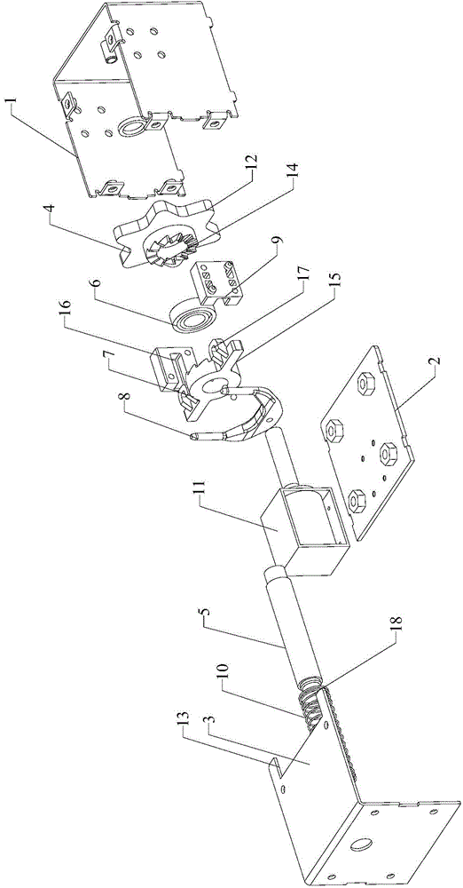
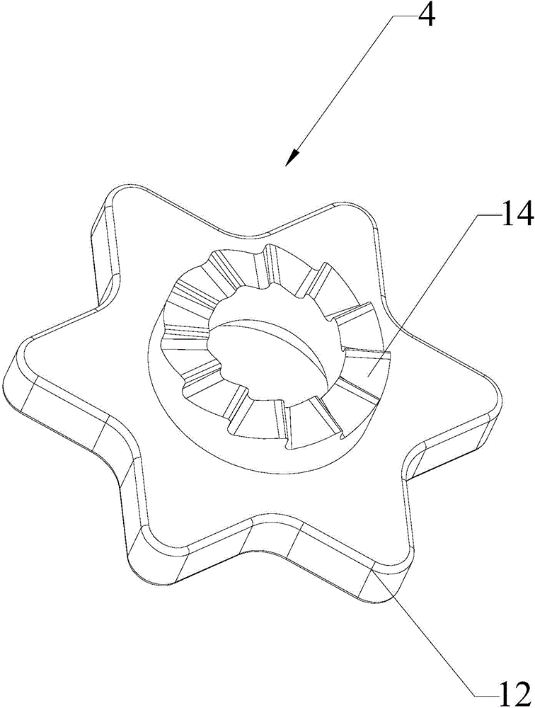
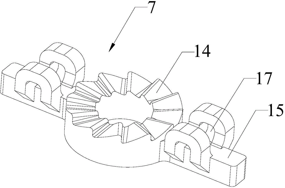
[0042] Please refer to Figure 4 , Embodiment 1 of the present invention is:
[0043] A lock used for public bicycles. Including the pole, the pole is provided with an annular groove and a card groove, and the annular groove includes a groove mouth 19 and a groove wall 20; the bicycle is provided with a closed surrounding pole 21, and by default, the surrounding pole of the bicycle 21 is locked between the raised corner of the hexagonal roller 4 and the groove mouth 19, thereby locking the bicycle. When people need to use the car, insert the special card into the card slot, so that the electromagnet 11 in the lock cylinder is energized to generate suction, and absorb the U-shaped magnetic metal pull rod on the fixed wheel 7, thereby pulling the fixed wheel 7 to move backward. , so that the one-way helical tooth 14 between the fixed wheel 7 and the roller 4 is disengaged, and the roller 4 can realize forward and reverse rotation, and the locked automatic car can be easily tak...
PUM
Abstract
The invention provides a mechanical rotating structure, which comprises a casing, a rolling wheel assembly, a fixed wheel assembly and an elastic assembly, wherein the rolling wheel assembly comprises a rolling wheel, a straight shaft and a bearing, the fixed wheel assembly comprises a fixed wheel, a magnetic metal element and a positioning element, the elastic assembly comprises an elastic element and an electromagnet, at least two bulge elements are arranged on the rolling wheel along the circumferential direction, the bulge elements of the rolling wheel exceed the surface of the casing, the rolling wheel and the fixed wheel are coaxially arranged on the straight shaft, the rolling wheel and the fixed wheel are fixedly connected through the matching by unidirectional inclined teeth, the two sides of the fixed wheel are respectively provided with convex rods, the positioning element is provided with chutes matched with the convex rods, the magnetic metal element is fixedly arranged on the fixed wheel, the elastic element is connected between the fixed wheel and the casing, the electromagnet is arranged at one side, near the elastic element, of the metal element, and in addition, a gap is formed between the electromagnet and the metal element. The mechanical rotating structure has the advantages that the structure is simple and ingenious, the size is small, the mechanical rotating structure can be better popularized and used, in addition, the safety performance is enhanced, and good application prospects are realized in the field of municipal engineering design.
Description
technical field [0001] The invention relates to the field of mechanical equipment, in particular to a mechanical rotating structure and a lock. Background technique [0002] In order to facilitate people's travel and promote green energy conservation and environmental protection, many places in the city are equipped with public bicycles for people to use for a fee. As a kind of public equipment, it not only needs to be convenient for people to take and return, but also needs to have a good anti-theft effect. However, many existing public bicycles need complicated switch and lock procedures, and the anti-theft effect is not very good. Therefore, it is necessary to provide a mechanical rotating structure and lockset with simple structure, convenient opening and closing of the lock, and good anti-theft effect. Contents of the invention [0003] The technical problem to be solved by the present invention is to provide a mechanical rotating structure and a lockset, which can s...
Claims
Application Information
Patent Timeline
Application Date:The date an application was filed.
Publication Date:The date a patent or application was officially published.
First Publication Date:The earliest publication date of a patent with the same application number.
Issue Date:Publication date of the patent grant document.
PCT Entry Date:The Entry date of PCT National Phase.
Estimated Expiry Date:The statutory expiry date of a patent right according to the Patent Law, and it is the longest term of protection that the patent right can achieve without the termination of the patent right due to other reasons(Term extension factor has been taken into account ).
Invalid Date:Actual expiry date is based on effective date or publication date of legal transaction data of invalid patent.