
Fuel assembly blending screenwork with rectifying type blending wings

A fuel assembly and mixing wing technology, applied in the field of reactor components, can solve the problems of increasing kinetic energy dissipation, weakening, disturbance, etc., and achieve the effects of improving thermal margin, reducing diversion, and increasing mixing length

Active Publication Date: 2015-04-01
CHINA NUCLEAR POWER TECH RES INST CO LTD +2
View PDF6 Cites 5 Cited by
  • Summary
  • Abstract
  • Description
  • Claims
  • Application Information

AI Technical Summary

Problems solved by technology

[0005] However, there are certain limitations in the structure of the mixing blades used in the prior art, which greatly reduces the effect of improving the thermal margin
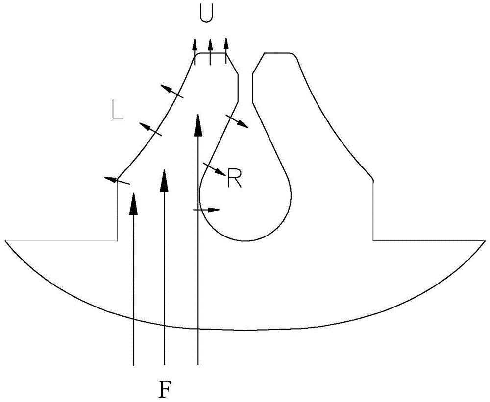
like image 3 As shown, the existing mixing blade is a triangular flat plate structure. When the coolant fluid F flows upward, it will directly hit the flat surface of the mixing blade, thereby generating a split flow. It is what we need, but the coolant fluid L and R diffused to the left and right along the surface of the stirring wing weakens the upward coolant flow, which is why the effect of the stirring wing on improving the thermal margin is reduced
In addition, the coolant fluid diffused left and right will disturb the surrounding flow field, increasing the invalid kinetic energy dissipation

Method used


Image

  • Fuel assembly blending screenwork with rectifying type blending wings
  • Fuel assembly blending screenwork with rectifying type blending wings
  • Fuel assembly blending screenwork with rectifying type blending wings

Examples


Embodiment Construction

[0029] The preferred embodiments of the present invention will be described below with reference to the accompanying drawings.

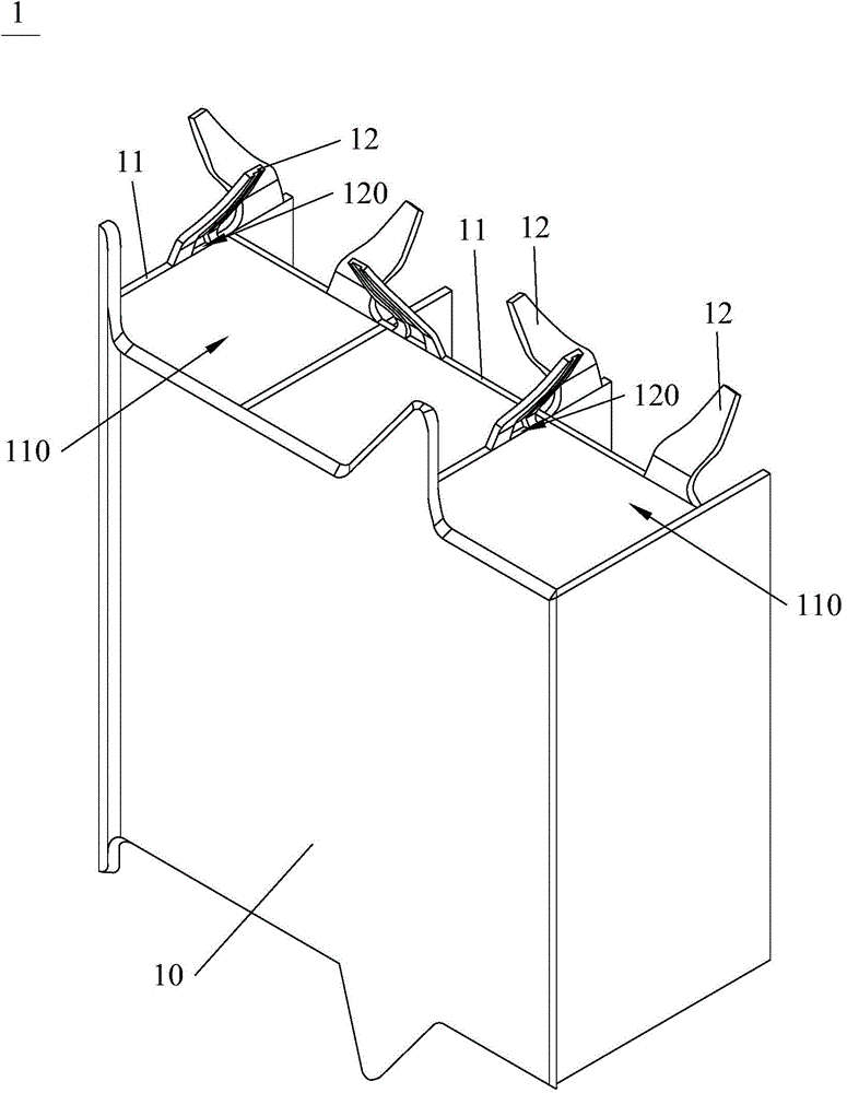
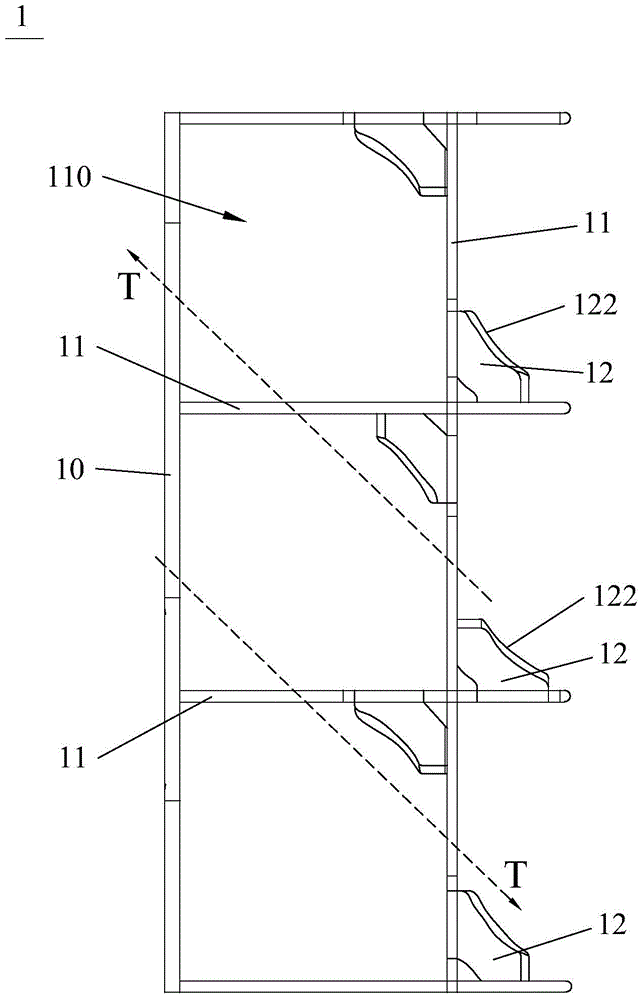
[0030] like figure 1 , figure 2 As shown, the fuel assembly stirring grid 1 with a rectifying type stirring blade of the present invention includes an outer strip 10 and a plurality of inner strips 11, and a plurality of the inner strips 11 intersect with each other to form a grid structure, and the grid structure There are a plurality of hollow grid units 110, the outer strip 10 surrounds the outer periphery of the grid structure and is fixed with the inner strip 11, the grid structure has a plurality of stirring wings 12, the stirring The wings 12 extend into the grill unit 110 , and a guide groove 120 is provided on the side of the stirring wing 12 facing the grill unit 110 .

[0031] The inner strips 11 are actually divided into two groups. One group of inner strips 11 is arranged parallel to each other and at equal intervals, and the other g...


PUM


Abstract

The invention discloses a fuel assembly blending screenwork with rectifying type blending wings. The fuel assembly blending screenwork comprises an outer strip and a plurality of inner strips, wherein the plurality of inner strips are intercrossed to form a grid structure, the grid structure is provided with a plurality of hollow grid units, the outer strip surrounds the periphery of the grid structure and is fixed together with the inner strips, the grid structure is provided with a plurality of blending wings, the blending wings are stretched into the grid units, and flow guide grooves are formed in the surfaces, facing to the interiors of the grid units, of the blending wings. The fuel assembly blending screenwork disclosed by the invention can be used for reducing the shunt phenomenon of a coolant towards the left and right sides of the blending wings, limiting the irregular flow of the fluid, playing a rectifying function and ensuring that the blending wings are used for improving the thermal balance effect of the fuel assembly.

Description

technical field [0001] The present invention relates to a reactor component, in particular to a fuel assembly stirring grid with a rectifying type stirring wing. Background technique [0002] A certain number of fuel rods are arranged at a certain interval (such as: 15×15 or 17×17, etc.) and are fixed into a bundle, which is called a reactor fuel assembly. Also called spacer grid), control rod guide tubes and fuel rods. Among them, the stirring grid is used for loading fuel rods and is composed of a plurality of inner strips and outer strips surrounding the inner strips. A plurality of inner strips intersect (generally orthogonally) to form a grid-like grid structure having a plurality of grid cells. [0003] As we all know, the chain reaction in the nuclear reactor will produce a large amount of radioactive substances harmful to human body, such as iodine 131, cesium 137, etc. In order to avoid the leakage of these radioactive substances, zirconium alloy shells, reactor p...

Claims


Application Information

Patent Timeline
Patent Type & Authority Applications(China)
IPC IPC(8): G21C3/322
CPCG21C3/322G21C3/34G21C3/3432G21C3/352Y02E30/30
Inventor 禹文池李伟才李现锋王仁钧聂立红陈晓明庞铮铮
Owner CHINA NUCLEAR POWER TECH RES INST CO LTD
Learn More