Reactor Core

a reactor core and core technology, applied in nuclear engineering, nuclear elements, greenhouse gas reduction, etc., can solve the problems of insufficient effect decrease of void fraction of fuel assembly, and inability to achieve sufficient effects on thermal margin improvement, etc., to suppress the increase in the power of a fuel assembly and increase the thermal margin of the core. , the effect of increasing the flow rate of coolan

Inactive Publication Date: 2009-02-12
HITACHI-GE NUCLEAR ENERGY LTD
View PDF3 Cites 7 Cited by
  • Summary
  • Abstract
  • Description
  • Claims
  • Application Information

AI Technical Summary

Benefits of technology

[0007]It is necessary to improve thermal margin by providing minimum change of the core system so as to improve power density of the core at low cost. Furthermore, extended cycle operation of the reactor is necessary to improve economical efficiency of fuel; inevitably, a large number of fuel assemblies loaded in the core must be exchanged after the operation cycle has been completed. Roughly, at least 25% of total number of fuel assemblies loaded in the core must be exchanged, and the batch number of fuel exchange is equal to or less than 4. This leads to the increase in the rate of new fuel assemblies that the in-core fuel dwelling time is a first cycle. Therefore, since the number of the fuel assemblies that power is high relatively increases in the core, thermal margin of the core reduces. Accordingly, it is necessary to ensure thermal margin by reducing the power of the fuel assemblies that the in-core fuel dwelling time is the first cycle and becoming flattened the peak of the power in the radial direction of the core.
[0008]To reduce power generation cost, it is effective to improve thermal margin by minimizing the change of the core system and improve power density. On the other hand, extended cycle operation is effective for the improvement of the operating rate of the nuclear power plant. In both cases, the number of fuel assemblies to be exchanged is large. Roughly, equal to or more than 25% of fuel assemblies in the core (4 batches or less) must be exchanged under the condition in which enrichment is limited to 5 wt % or less. As stated above, this means that the percentage of high power fuel assemblies relatively increases in the core and the percentage of fuel assemblies which have low thermal margin increases. As stated above, it is necessary to ensure thermal margin by reducing the power of the fuel assemblies that the in-core fuel dwelling time is the first cycle and becoming flattened the peak of the power in the radial direction of the core.
[0009]As a method for improving thermal margin, it is contemplated to use an apparatus for adjusting the flow rate of the cooling water (coolant) per the fuel assembly and provide a relative flow rate of the cooling water per the fuel assembly. Specifically, by reducing the resistance value of the orifice of the cooling water inlet located in the fuel support fitting into which the bottom of the fuel assembly, the thermal margin of which is to be improved, is inserted, it is possible to increase the flow rate of cooling water in the fuel assembly, the in-core fuel dwelling time of which is the first cycle, thereby improving the thermal margin.

Problems solved by technology

However, if the flow rate of the cooling water supplied to a fuel assembly increases, void fraction of the fuel assembly decreases and neutrons are easily moderated.
Therefore, sufficient effects on the improvement of thermal margin were not obtained.

Method used


Image

  • Reactor Core
  • Reactor Core
  • Reactor Core

Examples


embodiment 1

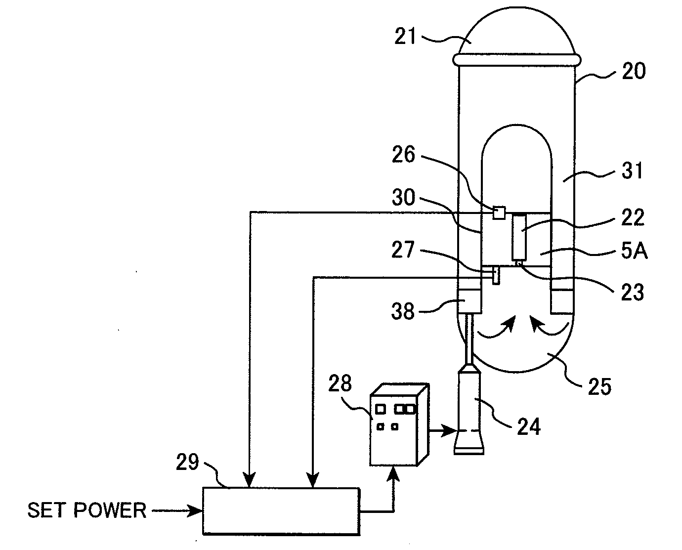
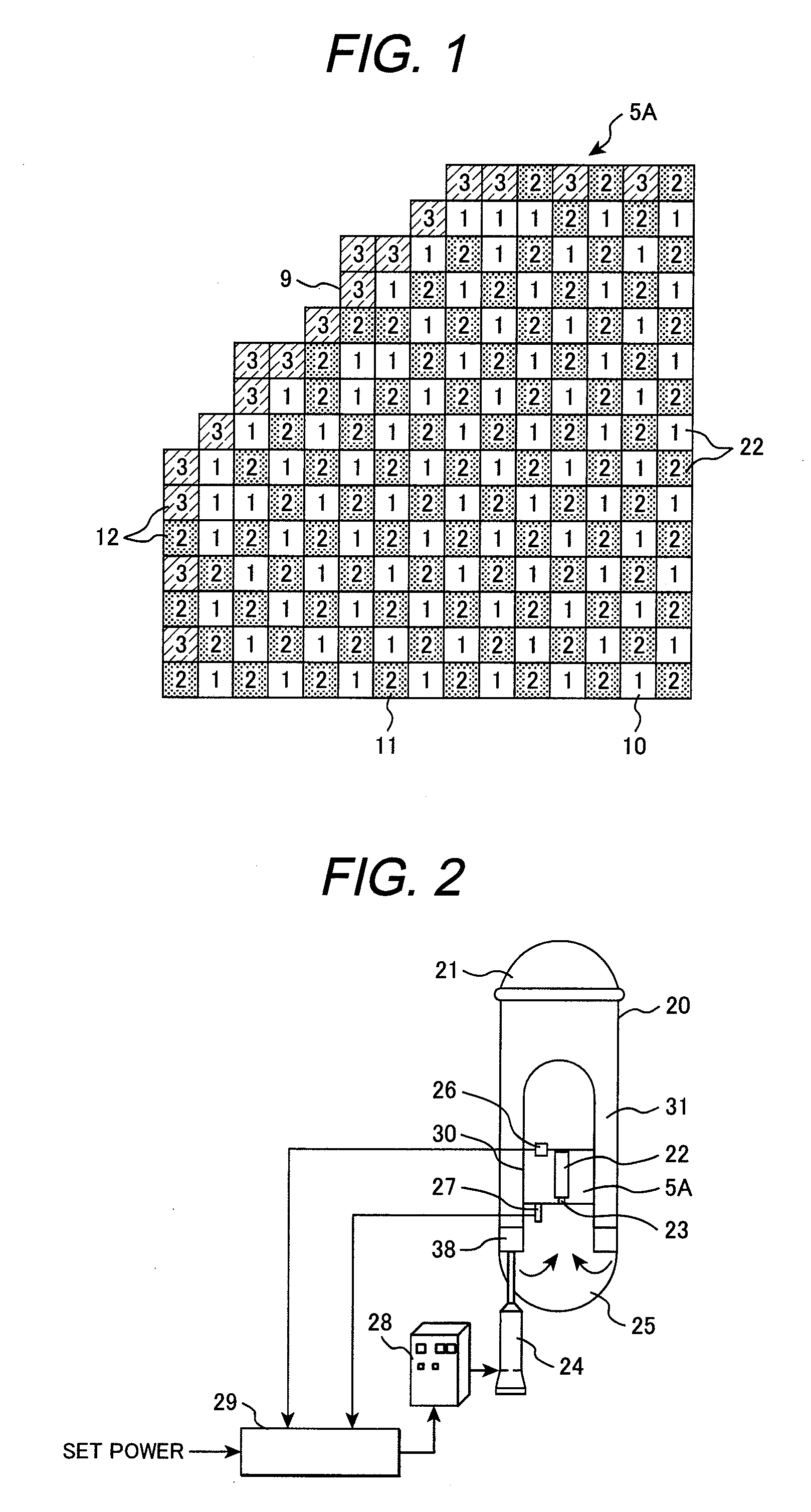
[0047]A reactor core applied to a Boiling Water Reactor (BWR) plant, which is a preferred embodiment of the present invention, will be explained with reference to FIGS. 1 to 3. First, structure of the BWR system to which the reactor core of the present embodiment is applied will be described. The BWR plant comprises a reactor 20 including a reactor pressure vessel (hereafter, referred to as RPV) 21, an inverter power supply apparatus 28 and a core flow rate control apparatus 29 and the like. The reactor 20 has the core 5A arranged in the RPV 21, and a neutron detector 26 and a flowmeter 27 are provided in the RPV 21. The core 5A is enclosed in the core shroud 30 provided in the RPV 21. A steam separator (not shown) and a dryer (not shown) are disposed at the upper part of the core 5A inside the RPV 21. A plurality of internal pumps 24 are installed in the RPV 21, an impeller 38 of each internal pump 24 is disposed in an annular down corner 31 formed between the RPV 21 and the core s...

embodiment 2

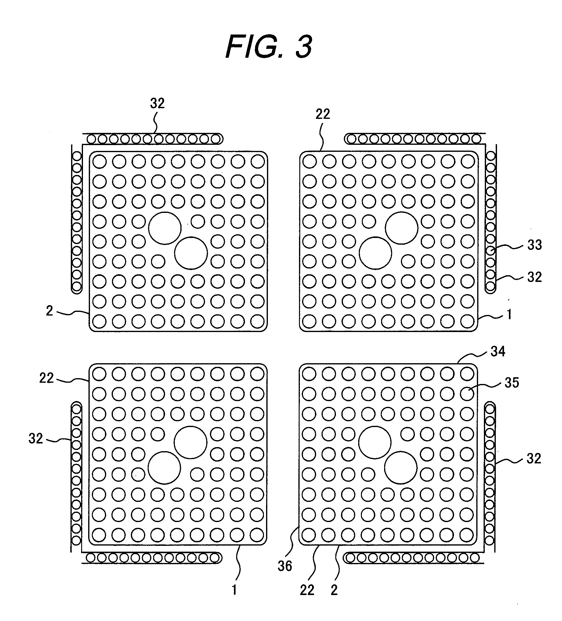
[0060]A reactor core of embodiment 2 applied to a BWR, which is another embodiment of the present invention, will be described with reference to FIG. 11. The BWR plant using the core 5B has a reactor 20 shown in FIG. 2 and equipped with the core 5B. In the core 5B of the present embodiment, a plurality of fuel assemblies 10 and 11 are arranged in the inner core region 7 in which fuel assemblies 22, each of which has the axis on the inner side of the L / √{square root over (2)} position from the center of the core 5B, are loaded, and instead of providing fuel assemblies 10, a plurality of fuel assemblies 11 are arranged in the outer core region 8 located between the inner core region 7 and the outermost layer region 9. The structure of other portions of the BWR plant incorporating the core 5B is the same as that of embodiment 1. A plurality of fuel assemblies 11 arranged in the outer core region 8 include fuel assemblies 1 and fuel assemblies 2. In most fuel assemblies 1 loaded in the ...

embodiment 3

[0063]A reactor core of embodiment 3 applied to a BWR, which is another embodiment of the present invention, will be described with reference to FIG. 12. In the core 5C of the present embodiment, fuel assemblies 10 and 11 are arranged in the inner core region 7 and the outer core region 8, respectively, which are surrounded by the outermost layer region 9. The BWR plant which incorporates the core 5C is an ABWR plant that has an ABWR as a reactor 20. The ABWR plant also has the same structure as that of BWR plant of the embodiment 1 shown in FIG. 2 except for the core 5C and a recirculation system. The ABWR has internal pumps instead of jet pumps. The core 5C is an ABWR type core.

[0064]Electric power of the ABWR plant is 1.35 million kW, and the core 5C is loaded with 872 fuel assemblies 22 that the average discharged burn-up is 45 GWd / t. There are provided 218 control rods 32, and hafnium type neutron absorption members are provided instead of neutron absorption rods 33. One operat...


PUM


Abstract

A reactor core, comprising:an outermost region; a core region surrounded by said outermost region; a plurality of fuel support members, each of which is disposed at a lower end portion of said outermost region and said core region; and a plurality of fuel assemblies loaded in said outermost region and said core region and supported by said fuel support members,wherein a plurality of fuel assemblies disposed in said core region include a plurality of first fuel assemblies, each of which is inserted into a first coolant passage which is formed in said fuel support member and has a first resistor having an opening, and a plurality of second fuel assemblies, each of which is individually inserted into each of second coolant passage which is formed in said fuel support member and has a second resistor having an opening and a larger pressure loss than that of said first resistor; and,four fuel assemblies, each of which is adjacent to each of four lateral sides of each of a plurality of first fuel assemblies, include either three or four second fuel assemblies.

Description

CLAIM OF PRIORITY[0001]The present application claims priority from Japanese Patent application serial no. 2007-208255, filed on Aug. 9, 2007, the content of which is hereby incorporated by reference into this application.BACKGROUND OF THE INVENTION[0002]The present invention relates to a reactor core, and more particularly, to a reactor core suitable for the use in a Boiling Water Reactor having an apparatus for adjusting cooling water flow rate.[0003]A fuel assembly used for a Boiling Water Reactor (BWR) includes a plurality of fuel rods and a channel box. Each of the fuel rods is filled with a plurality of fuel pellets including fissile material in the cladding tube, are bundled in a square lattice form. The square channel box encloses the bundled fuel rods. The square channel box has an outer width of about 14 cm and a square cross-section. A core, which is disposed in the reactor pressure vessel of a BWR, is loaded with a plurality of fuel assemblies internally. For nuclear fue...

Claims


Application Information

Patent Timeline
Patent Type & Authority Applications(United States)
IPC IPC(8): G21C15/06
CPCG21C3/322Y02E30/38G21Y2004/302G21C15/02Y02E30/30
Inventor MITSUYASU, TAKESHIAOYAMA, MOTOOISHII, KAZUYACHAKI, MASAO
Owner HITACHI-GE NUCLEAR ENERGY LTD
Why Eureka
Try Eureka