Tomato beater
A technology of beating machine and tomato, applied in the direction of solid separation, filter screen, grille, etc., can solve the problems of low pulp output and poor crushing effect.
- Summary
- Abstract
- Description
- Claims
- Application Information
AI Technical Summary
Problems solved by technology
Method used
Image

Examples
Embodiment Construction
[0011] The present invention will be described in further detail below by means of specific embodiments:
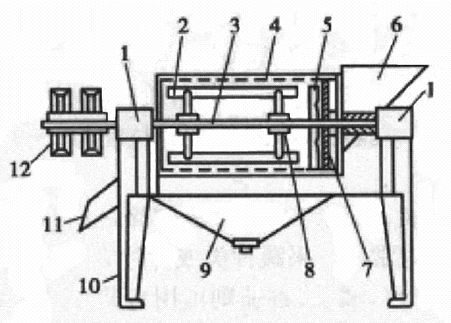
[0012] The reference signs in the accompanying drawings of the description include: bearing 1, upper scraper 2, rotating shaft 3, cylindrical screen 4, paddle 5, feed hopper 6, screw propeller 7, gripper 8, collection box 9, machine Frame 10, slag hopper 11, transmission system 12.
[0013] as attached figure 1 Shown: the lower part of the frame 10 is provided with four legs along the length direction of the frame 10, and the upper part of the frame 10 is provided with two semicircular bearing support seats along the length direction of the frame 10, and the bearing 1 support seat Two bearings are installed on it, and the bearing 1 is supported with a rotating shaft 3 along the length direction of the frame 10, and the rotating shaft 3 is connected with the transmission system 12, and the present embodiment adopts double pulley transmission. Specifically, the transmissi...
PUM
 Abstract
Description
Claims
Application Information
 - Generate Ideas
- Intellectual Property
- Life Sciences
- Materials
- Tech Scout
- Unparalleled Data Quality
- Higher Quality Content
- 60% Fewer Hallucinations
Browse by: Latest US Patents, China's latest patents, Technical Efficacy Thesaurus, Application Domain, Technology Topic, Popular Technical Reports.
© 2025 PatSnap. All rights reserved.Legal|Privacy policy|Modern Slavery Act Transparency Statement|Sitemap|About US| Contact US: help@patsnap.com