
Oxygen supply apparatus with pressure relief function

A technology of oxygen supply and function, applied in the direction of respirator, etc., can solve the problem of no decompression and inflation function, and achieve the effect of avoiding damage

Inactive Publication Date: 2015-04-08
AONENG LIGHTING CO LTD +1
View PDF10 Cites 4 Cited by
  • Summary
  • Abstract
  • Description
  • Claims
  • Application Information

AI Technical Summary

Problems solved by technology

However, this pneumatic oxygen storage device still has deficiencies, mainly because there is no decompression and inflation function, so it needs to be improved

Method used


Image

  • Oxygen supply apparatus with pressure relief function
  • Oxygen supply apparatus with pressure relief function
  • Oxygen supply apparatus with pressure relief function

Examples


Embodiment Construction

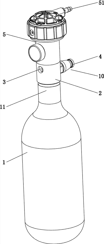
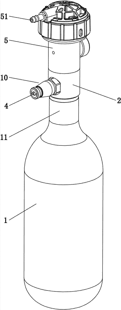
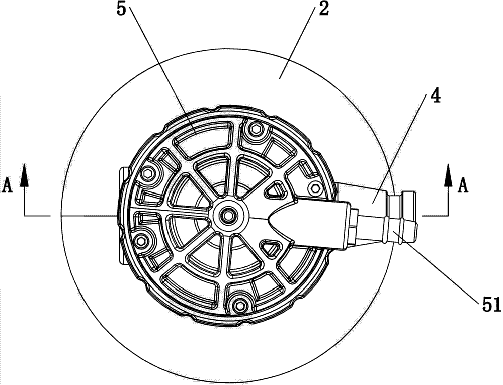
[0028] The present invention will be further described below in conjunction with accompanying drawing and embodiment:

[0029] see Figure 1 to Figure 8 As shown, an oxygen supplier with decompression function includes an oxygen economizer 5 provided with an oxygen inlet 52 and an oxygen outlet 51 , and the oxygen inlet 52 is provided with a decompression device 3 .

[0030] The decompression device 3 includes a valve body 2 and a decompression switch. The valve body 2 is provided with an oxygen inlet passage 21 and an oxygen outlet passage 22. The oxygen inlet passage 21 is used to connect with the oxygen container 1. The oxygen inlet 52 of 5 communicates, and the decompression switch is arranged between the oxygen inlet channel 21 and the oxygen outlet channel 22.

[0031] The diameter of the oxygen inlet channel 21 is larger than the diameter of the oxygen outlet channel 22 .

[0032] The decompression switch includes a valve core 31 and a valve plate 32, and the valve bo...


PUM


Abstract

The invention relates to an oxygen supply apparatus with a pressure relief function. The oxygen supply apparatus comprises an oxygen economizer with an oxygen inlet and an oxygen outlet, and the oxygen inlet is provided with a pressure reliever. The oxygen supply apparatus is provided with a pressure relief switch, so that when an oxygen container has large gas pressure as being full of oxygen, pressure can be limited by regulating opening of the pressure relief switch so as to protect an oxygen economizer of the oxygen supply apparatus.

Description

technical field [0001] The invention relates to portable oxygen supply equipment, in particular to an oxygen supply device with decompression function. Background technique [0002] U.S. Patent No. US6484721B1 disclosed a pneumatic oxygen storage device on November 26, 2002, which can effectively deliver oxygen or other gases during medical procedures, allowing patients to inhale oxygen or other medical gases at the initial stage of inhalation. When the patient begins to inhale, using a pneumatic oxygen storage device, a short exhaust flow continues to the patient after the first established inhalation to prevent multiple oxygen pulses. However, the pneumatic oxygen storage device still has deficiencies, mainly because it does not have decompression and inflation functions, so it needs to be improved. Contents of the invention [0003] The purpose of the present invention is to overcome the shortcomings in the above-mentioned prior art structure, and provide a simple and ...

Claims


Application Information

Patent Timeline
Patent Type & Authority Applications(China)
IPC IPC(8): A61M16/00A61M16/20
Inventor 朱敏
Owner AONENG LIGHTING CO LTD
Learn More