
Valveless filter with lift breaking bucket

A valveless filter and destruction bucket technology, applied to loose filter material filters, gravity filters, filter separation, etc., can solve problems affecting normal work and achieve the effect of prolonging the use time

Active Publication Date: 2015-04-08
上海智楹科技有限公司
View PDF6 Cites 1 Cited by
  • Summary
  • Abstract
  • Description
  • Claims
  • Application Information

AI Technical Summary

Problems solved by technology

[0003] The height of the destruction bucket controls the length of the backwashing time. The new filter material needs a shorter backwashing time. With the increase of the number of filtrations, more and more sediments are attached to the filter material. If the washing time remains unchanged, The frequency of flushing becomes faster and faster, and finally affects its normal work. In order to work normally, the filter material has to be replaced

Method used


Image

  • Valveless filter with lift breaking bucket
  • Valveless filter with lift breaking bucket

Examples


Embodiment Construction

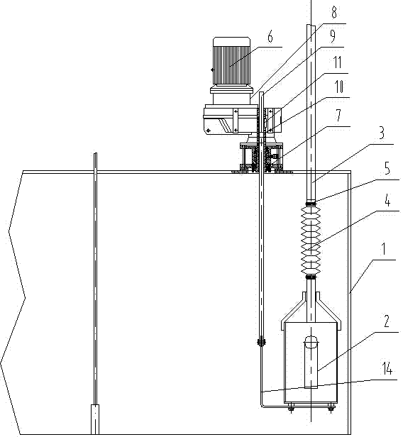
[0012] Such as figure 1 , 2 As shown, the filter tank 1 is included, the filter tank 2 is provided with a destruction bucket 2, the destruction bucket 2 is connected to the siphon destruction pipe 3 through the expansion joint 4, and the expansion joint 4 is respectively connected to the destruction bucket 2 and the siphon destruction pipe 3 through the hoop 5, and the filter A control machine mechanism 6 for controlling the lifting of the destruction bucket is installed on the tank 2 .

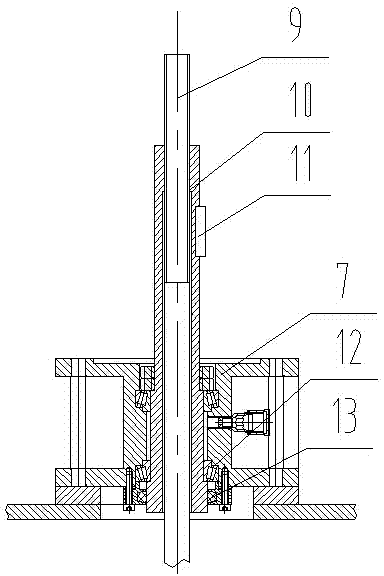
[0013] The control mechanism 6 includes a bearing seat 7, a reducer 8, a screw 9 and a nut 10. The bearing seat 7 is sealed and connected to the upper surface of the filter tank 1. The reducer 8 is installed on the bearing seat 7. The upper part of the nut 10 is connected by a key 11. At the output end of the reducer 8, the lower part of the nut 10 is connected with the bearing seat 7 through the bearing 12, and a sealing ring 13 is arranged between the lower end of the bearing seat 7 an...


PUM


Abstract

The invention relates to a valveless filter with a lift breaking bucket, and relates to a valveless filter. The valveless filter comprises a filter tank, wherein the breaking bucket is arranged in the filter tank, the breaking bucket is connected with a siphon breaking pipe. The valveless filter is characterized in that the breaking bucket is connected with the siphon breaking pipe through a telescopic joint, and a control mechanism for controlling the breaking bucket to rise and fall is installed on the filter tank. A nut is driven by a reducer to rotate, and a lead screw drives the breaking bucket to move up and down through the rotation of the nut so as to adjust the height of the breaking bucket.

Description

technical field [0001] The invention relates to a valveless filter, in particular to a valveless filter with a lifting destroying bucket. Background technique [0002] When the valveless filter is working, the raw water is sent into the filter through the water inlet pipe and filtered from top to bottom through the filter layer, and the clean water is poured into the flushing water tank from the connecting pipe for storage. The layer keeps intercepting suspended matter, which causes the resistance of the filter layer to increase continuously, so that the water level in the siphon tube continues to rise. When the water level reaches the siphon auxiliary port, a siphon effect occurs. At this time, the water in the water tank passes through the filter from bottom to top. When the water in the flushing water tank falls to the siphon breaking bucket, the air enters the siphon breaking bucket to break the siphon effect, and the backwashing of the filter is completed and enters the...

Claims


Application Information

Patent Timeline
Patent Type & Authority Applications(China)
IPC IPC(8): B01D24/46B01D24/48
Inventor 吉祥陈竹李军何志刚
Owner 上海智楹科技有限公司
Learn More