
Steering and shifting device of moving trolley

A mobile device and mobile trolley technology, applied in metal processing equipment, forming tools, manufacturing tools, etc., can solve the problems of high gear processing and installation requirements, high oil cylinder configuration cost, inconvenient installation and maintenance, etc., and achieve transmission stability. High, low cost, convenient installation and maintenance

Inactive Publication Date: 2015-04-08
CHINFONG CHINA MECHANICAL IND LIMITED
View PDF9 Cites 2 Cited by
  • Summary
  • Abstract
  • Description
  • Claims
  • Application Information

AI Technical Summary

Problems solved by technology

The steering and moving device of the above-mentioned mobile trolley needs to install four lifting oil cylinders at the turning point of the track, but the configuration cost of the oil cylinders is high, the quality stability is not high, and because the oil cylinders are installed in the foundation, it is inconvenient to install and maintain; in addition, Since the mobile trolley uses bevel gears to transmit power, eight sets of gears are required during the entire moving process, which requires relatively high processing and installation requirements for the gears, and the processing cost is high and maintenance is inconvenient.

Method used


Image

  • Steering and shifting device of moving trolley
  • Steering and shifting device of moving trolley
  • Steering and shifting device of moving trolley

Examples


Embodiment Construction

[0015] The present invention will be further described in detail below in conjunction with the accompanying drawings and embodiments.

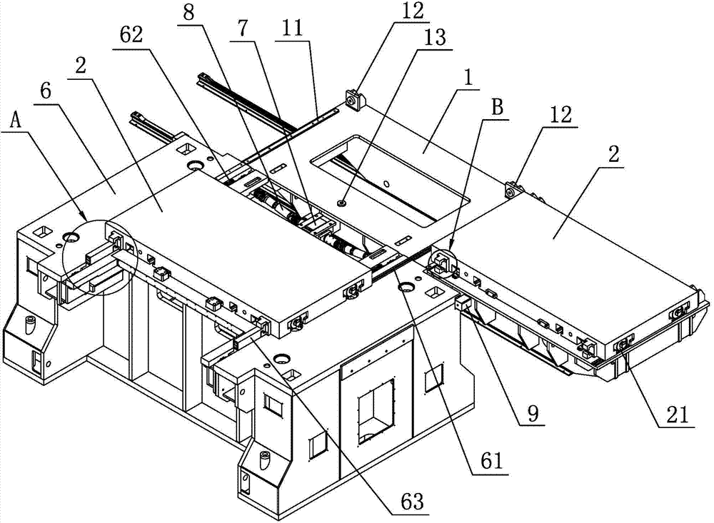
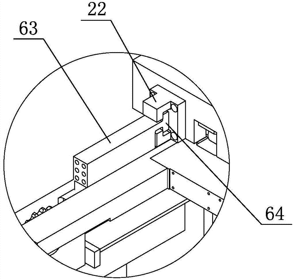
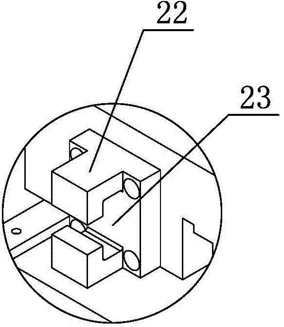
[0016] As shown in the figure, a steering and moving device for a mobile trolley includes a mobile trolley 1 that moves left and right along the foundation. Two worktables 2 are arranged side by side on the mobile trolley 1, and rollers 21 are provided on the lower end surface of the workbench 2. The upper end surface of the trolley 1 is fixedly provided with two sets of first rails 11 that match the rollers 21 side by side. The first guide rails 11 extend forward and backward and are perpendicular to the moving direction of the mobile trolley 1 . A positioning mechanism is arranged between them, and the positioning mechanism includes an in-position block 12 and a positioning pin 13. The in-position block 12 is fixedly arranged on the upper end surface of the mobile trolley 1 and is located on the rear side of the workbench 2, and the positioni...


PUM


Abstract

The invention discloses a steering and shifting device of a moving trolley. The steering and shifting device is characterized by comprising the moving trolley moving left and right along a base, wherein two workbenches are arranged on the moving trolley side by side; rollers are arranged on the lower end faces of the workbenches; two groups of first rails matched with the rollers side by side are fixedly arranged on the upper end face of the moving trolley; the first guide rails extend in the front and back direction and are perpendicular to the moving direction of the moving trolley; a positioning mechanism is arranged between the workbenches and the moving trolley; a trolley movement driving mechanism is arranged inside the moving trolley; a workbench movement driving mechanism for driving the workbenches to move front and back is arranged on a punch pedestal. The steering and shifting device can directly drive the workbenches to move front and back to the punch pedestal instead of moving the trolley front and back; compared with the conventional steering and shifting device, the steering and shifting device can eliminate a hoisting oil cylinder, so as to lower the cost and avoid maintenance to the oil cylinder; furthermore, the workbench movement driving mechanism adopts the motor and chains, so that the steering and shifting device is high in transmission stability, simple in structure, convenient to mount and maintain, and low in cost.

Description

technical field [0001] The invention relates to a mobile trolley used for mold replacement in punch processing, in particular to a steering and moving device for the mobile trolley. Background technique [0002] The mobile trolley is a commonly used equipment for changing molds in punch processing. It consists of a worktable and a mobile trolley. When the punching machine needs to change the mold, first remove the mobile trolley and the mold in the punching machine, and then move the mobile trolley with another pair of molds into the punching machine, and the mobile trolley needs to move at 90 degrees during this movement process. Turn to move. At present, the steering movement of the mobile trolley is basically provided with front and rear rails and left and right rails with a height difference in the foundation. The oil cylinder lifts the mobile trolley to ensure that the wheel height of the mobile trolley matches the height of the left and right rails, and then the mob...

Claims


Application Information

Patent Timeline
IPC IPC(8): B21D37/14
CPCB21D37/147
Inventor 孟卫校曾盛明郭丰平
Owner CHINFONG CHINA MECHANICAL IND LIMITED
Learn More