Spherical object limiting jig

A kind of article and spherical technology, applied in the field of limit fixtures, can solve the problems of inconvenient limit, high production cost, damage, etc., and achieve the effect of increasing limit stability, reducing production cost, and saving space occupation

Inactive Publication Date: 2015-04-08
WUJIANG GERUIFU HARDWARE
View PDF8 Cites 1 Cited by
  • Summary
  • Abstract
  • Description
  • Claims
  • Application Information

AI Technical Summary

Problems solved by technology

[0002] Due to the special curved surface shape, spherical objects are easy to roll and shift, so it is inconvenient to limit the position, and it is also easy to cause damage due to collision
There are some bowl-shaped limit fixtures. Although the internal shape conforms to the shape of spherical objects and the positioning is relatively stable, the number of spherical objects that can be stored is small, and the production cost is relatively high.

Method used


Image

  • Spherical object limiting jig
  • Spherical object limiting jig
  • Spherical object limiting jig

Examples


Embodiment 1

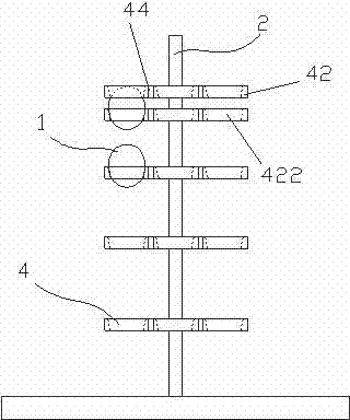
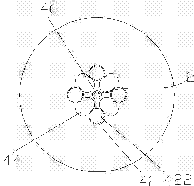
[0023] like Figure 1-2 As shown, a spherical article limit fixture includes a main support frame 2 extending in the height direction, and a five-layer auxiliary support frame 4 arranged on the main support frame 2. The auxiliary support frame 4 is provided with a The four accommodating holes 422 are distributed, and the upper opening diameter of the accommodating hole 422 is larger than the lower opening diameter, and the upper opening diameter is smaller than the maximum cross-sectional size of the spherical object 1 .

[0024] The auxiliary support frame 4 specifically includes four ring-shaped and evenly distributed snap rings 42, the inner circumference of the snap rings 42 forms accommodating holes 422, and a reinforcement connecting the two snap rings 42 is provided between adjacent two snap rings 42. Rib 44 is conducive to improving the overall strength.

[0025] The five-layer sub-support frames 4 are sleeved on the rod-shaped main support frame 2 through rubber ring...

Embodiment 2

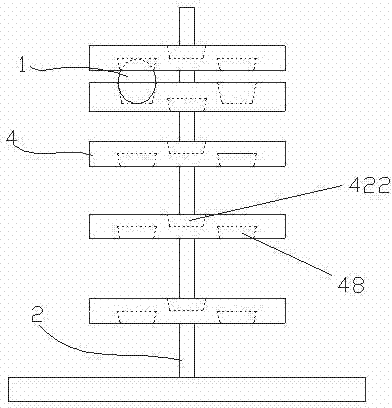
[0029] like Figure 3-4 As shown, a spherical object position limiting jig differs from Embodiment 1 in that the sub-support frames 4 of each layer are disc-shaped. An accommodating hole 422 is provided at the top of the auxiliary support frame 4 , and a groove 48 is provided at the bottom. The accommodating holes 422 and grooves 48 on each sub-support frame 4 are arranged at intervals along the circumferential direction. And the groove 48 of the uppermost sub-support frame 4 corresponds to the accommodating hole 422 of the adjacent lower sub-support frame 4 , so the spherical object 1 accommodated in the lower accommodating hole 422 can be clamped up and down.

[0030] When using the jig for limiting spherical objects in this embodiment, the spherical objects 1 can be placed in the accommodating holes 422 of any sub-support frame 4 to obtain the positioning. Further, the uppermost sub-support frame 4 can be pressed down, so that the corresponding upper layer groove 48 holds...


PUM


Abstract

The invention discloses a spherical object limiting jig. The spherical object limiting jig is characterized by comprising a main supporting rack and a plurality of secondary supporting racks, wherein the main supporting rack extends in the height direction; the secondary supporting racks are arranged on the main supporting rack; a plurality of accommodating holes which are distributed surrounding the main supporting rack are formed in the secondary supporting racks; and the diameter of an opening of the upper portion of each accommodating hole is greater than that of an opening of the lower portion of the accommodating hole, and is smaller than the maximum section size of a spherical object. The spherical object limiting jig is provided with the secondary supporting racks, each secondary supporting rack is provided with the accommodating holes which are distributed surrounding the main supporting rack, stability and storing and taking convenience are guaranteed, the capacity of the spherical object limiting jig on spherical objects is greatly improved, space is saved, and the manufacturing cost is reduced. Particularly, the diameter of the opening of the upper portion of each accommodating hole is greater than that of the opening of the lower portion of the accommodating hole, so that the spherical object limiting jig is stable when the spherical objects are accommodated in the spherical object limiting jig.

Description

technical field [0001] The invention relates to a position limiting jig. Background technique [0002] Due to the special curved surface shape, spherical objects are easy to roll and shift, so it is inconvenient to limit the position, and it is also prone to collision and damage. There are some existing bowl-shaped limit fixtures. Although the internal shape conforms to the shape of spherical objects and the positioning is relatively stable, the number of spherical objects that can be stored is small, and the production cost is relatively high. Contents of the invention [0003] A spherical article limiting jig is characterized in that it includes a main support frame extending in the height direction, and a multi-layer auxiliary support frame arranged on the main support frame, and the auxiliary support frame is provided with a A plurality of accommodating holes are distributed, the upper opening diameter of the accommodating holes is larger than the lower opening diamet...

Claims


Application Information

Patent Timeline
Patent Type & Authority Applications(China)
IPC IPC(8): B25H3/04
CPCB25H3/04
Inventor 刘鹭
Owner WUJIANG GERUIFU HARDWARE
Why Eureka
Try Eureka