
Two-stroke stratified scavenging engine

An engine and two-stroke technology, which is applied in the field of two-stroke layered scavenging engines, can solve problems such as unsatisfactory application prospects, installation space and cost constraints, and achieve the effects of sufficient scavenging, thorough ventilation, and reduced short-circuit losses

Active Publication Date: 2015-04-08
JIANGSU LINHAI POWER MACHINERY GROUP
View PDF5 Cites 10 Cited by
  • Summary
  • Abstract
  • Description
  • Claims
  • Application Information

AI Technical Summary

Problems solved by technology

Fuel injection technology is one of the most effective measures to reduce the short-circuit loss of two-stroke engines, but its application prospect is not ideal in small non-road gasoline engines due to the limitation of installation space and cost

Method used


Image

  • Two-stroke stratified scavenging engine
  • Two-stroke stratified scavenging engine
  • Two-stroke stratified scavenging engine

Examples


Embodiment 1

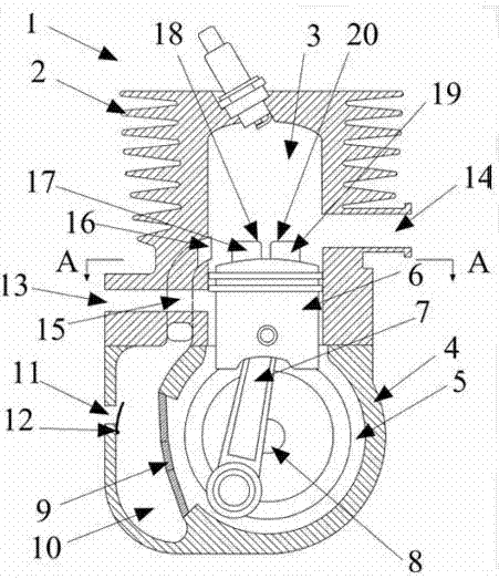
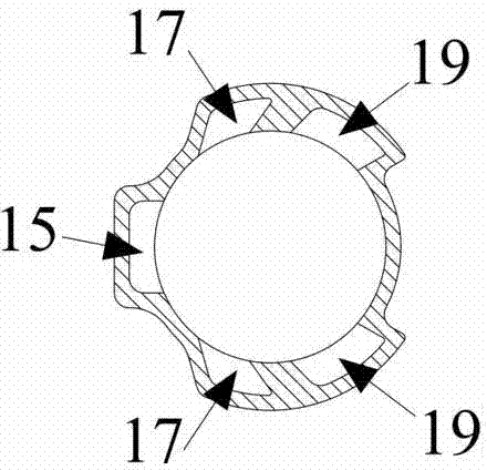
[0030] The invention as figure 1 , figure 2 As shown, a two-stroke stratified scavenging engine, the main technical solution

[0031] Yes, including: cylinder block 2, body 4, crankcase 5, piston 6, crankshaft 8, air scavenging components and mixed gas scavenging components, the air scavenging components are mainly composed of a diaphragm 9 fixedly connected to the body 4 It is composed of the air storage cavity 10 and the air scavenging channel 15 formed by the inner wall of the body 4, and the two ends of the air scavenging channel 15 are respectively connected with the air scavenging port 16 and the air storage cavity arranged on the inner wall of the cylinder body 2. 10 connected. The mixed gas scavenging component mainly includes mixed gas scavenging channels 17, 19, and the mixed gas scavenging channels 17, 19 are cavities jointly formed by the outer surface of the piston 6 and the grooves provided on the inner wall of the cylinder 2 The two ends of the mixed gas s...

Embodiment 2

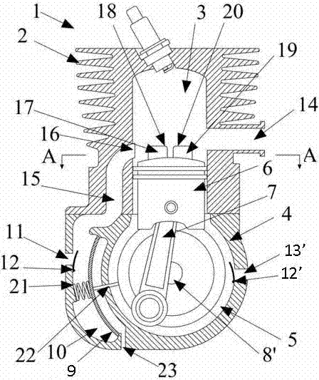
[0039] The invention as figure 1 , figure 2 , image 3 As shown, a two-stroke stratified scavenging engine, the main technical solution is to include: cylinder block 2, body 4, crankcase 5, piston 6, crankshaft 8', air scavenging components and mixed gas scavenging components, The air scavenging part is mainly composed of an air storage cavity 10 and an air scavenging channel 15 formed by the diaphragm 9 fixedly connected to the body 4 and the inner wall of the body 4, and the two ends of the air scavenging channel 15 are respectively connected to The air scavenging port 16 provided on the inner wall of one side of the cylinder body 2 communicates with the air storage cavity 10 . The mixed gas scavenging component mainly includes mixed gas scavenging channels 17, 19, and the mixed gas scavenging channels 17, 19 are cavities jointly formed by the outer surface of the piston 6 and the grooves provided on the inner wall of the cylinder 2 The two ends of the mixed gas scaven...


PUM


Abstract

The invention discloses a two-stroke stratified scavenging engine mainly comprising an air scavenging part and a mixed gas scavenging part. The air scavenging part mainly comprises an air storage chamber (10) and an air scavenging passage (15); two ends of the air scavenging passage (15) are communicated with an air scavenging orifice (16) arranged in the inner wall of one side of a cylinder block (2) and the air storage chamber (10); the mixed gas scavenging part mainly comprises mixed gas scavenging passages (17 and 19); the mixed gas scavenging passages are hollow passages formed by the outer surface of a piston (6) and grooves arranged in the inner wall of the cylinder block (2); two ends of the mixed gas scavenging passages (17 and 19) are communicated with mixed gas scavenging orifices (18 and 20) arranged in a cylinder (3) and a crankcase (5). The technical scheme of stratified scavenging with the independent air scavenging passages is provided, short-circuit loss of fresh mixed gas is greatly reduced, and harmful emission of the engine is reduced.

Description

technical field [0001] The present invention relates to The field of engine technology, specifically It relates to a two-stroke stratified scavenged engine. Background technique [0002] High-speed small-displacement two-stroke engines have the advantages of high mechanical efficiency, high specific power and low cost, and occupy a huge market space in the fields of agriculture, forestry, construction, garden plant protection, sports and entertainment. However, in recent years, under the dual pressure of energy and environmental issues, governments of various countries have introduced increasingly stringent emission regulations. Due to the impact of factors such as economy and poor emission performance of two-stroke gasoline engines, especially HC+NO x And CO emissions, causing serious environmental pollution, its development has been limited. The main reason for the poor emission of the two-stroke gasoline engine is the incomplete ventilation process: on the one hand, the...

Claims


Application Information

Patent Timeline
IPC IPC(8): F02B25/14F02B25/22
CPCY02T10/12
Inventor 刘梁袁晓春黄勇
Owner JIANGSU LINHAI POWER MACHINERY GROUP
Learn More