Multi-purpose bladeless fan

A bladeless fan and multi-functional technology, applied in pump control, non-variable pumps, pump devices, etc., can solve the problems of high wind speed stability, adjustable wind speed, high wind speed, etc.

Inactive Publication Date: 2015-04-08
UNIV OF SHANGHAI FOR SCI & TECH
View PDF7 Cites 12 Cited by
  • Summary
  • Abstract
  • Description
  • Claims
  • Application Information

AI Technical Summary

Problems solved by technology

When using a bladeless fan in daily life, because the user cannot adjust the wind speed according to his own needs, the wind speed will be too high or too low, which makes the user feel very uncomfortable
When used in industrial fields, such as laboratories, it is often necessary to pre-set the wind speed, and the stability of the wind speed is high, and the current bladeless fan obviously cannot meet the demand

Method used


Image

  • Multi-purpose bladeless fan
  • Multi-purpose bladeless fan
  • Multi-purpose bladeless fan

Examples


Embodiment 1

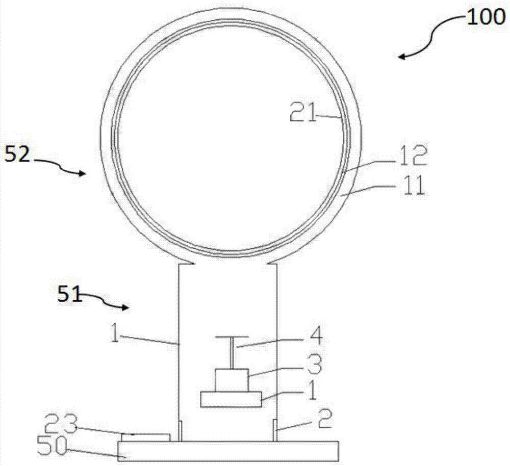
[0020] figure 1 It is a structural schematic diagram of the multifunctional bladeless fan of the present invention in Embodiment 1.

[0021] Such as figure 1 As shown, the multifunctional bladeless fan 100 of this embodiment includes a base 50 , a base part 51 , a nozzle part 52 and a wind speed regulating part. The base part 51 is provided above the base 50 . The nozzle portion 52 is provided above the base portion 51 . The nozzle part 52 communicates with the base part 51 and can receive the airflow from the base part 51 .

[0022] The nozzle portion 52 includes an airflow passage and an airflow generating unit. The airflow channel is a cylindrical shell 1, and air inlets 2 are arranged on both sides of the lower end of the shell 1.

[0023] The airflow generating unit includes a motor 3 and an impeller 4 . The motor 3 can drive the impeller 4 to rotate at a high speed, and the air is sucked into the shell 1 from the air inlet 2 . After the airflow is accelerated by t...

Embodiment 2

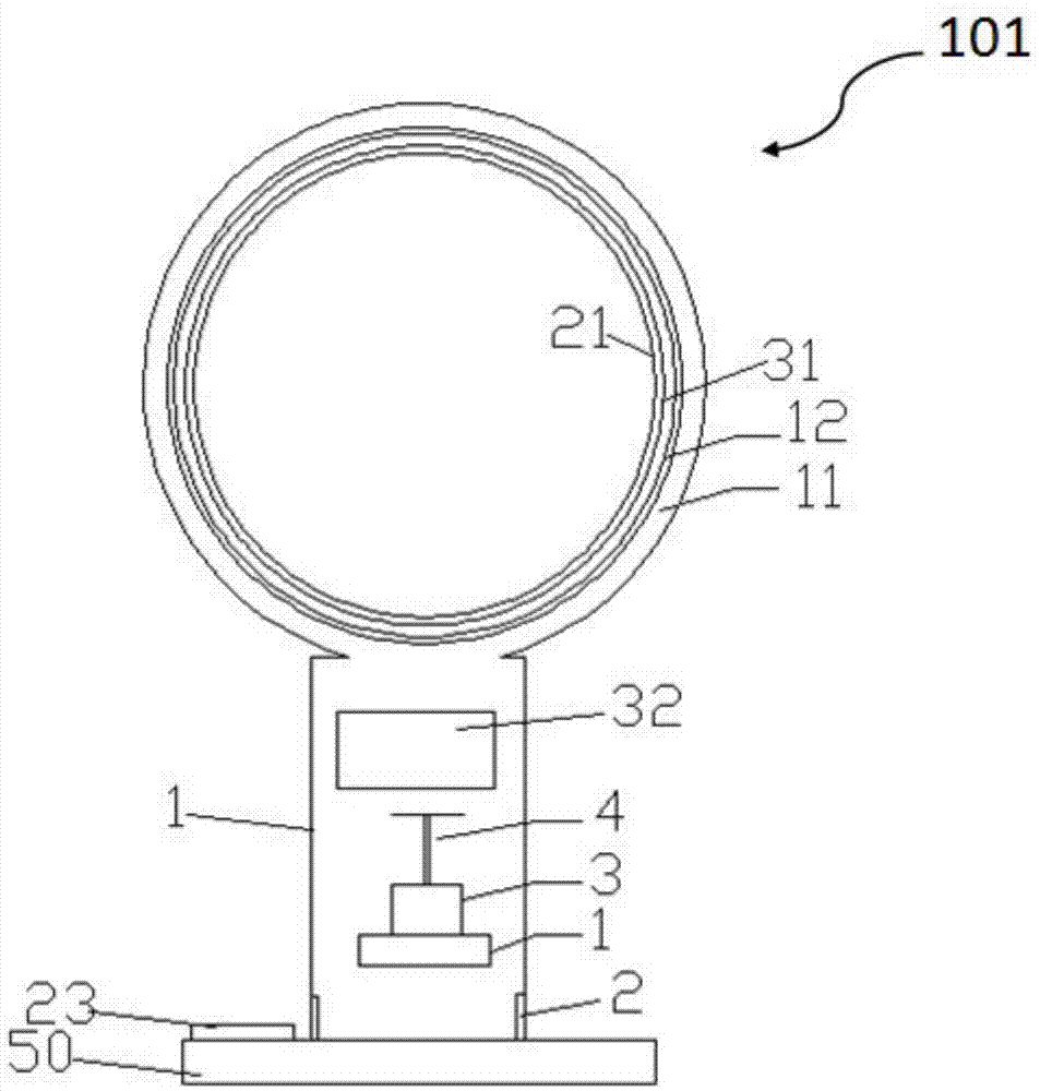
[0032] figure 2 It is a structural schematic diagram of the second embodiment of the multifunctional bladeless fan of the present invention. figure 2 kept figure 1 The same structure in , uses the same number.

[0033] Such as figure 2 As shown, the multifunctional bladeless fan 101 of this embodiment includes a base part 51 , a nozzle part 52 , a wind speed regulating part, and a temperature regulating part.

[0034] The temperature regulating part includes a heating wire 31 and an ice storage tank 32 . The heating wire 31 is arranged inside the air outlet 12 and forms a ring. The heating wire 31 is connected with the controller 22 through a circuit. A heating button is arranged on the control panel. When the heating button is pressed to the heating state, the controller 22 will control the heating wire 31 to work, thereby heating the airflow emitted from the air outlet 12 and blowing warm air.

[0035] The ice storage tank 32 is arranged inside the casing 1 and has...

Embodiment 3

[0039] image 3 It is a structural schematic diagram of the second embodiment of the multifunctional bladeless fan of the present invention. image 3 kept figure 1 The same structure in , uses the same number.

[0040] Such as image 3 As shown, the multifunctional bladeless fan 102 of this embodiment includes a base part 51 , a nozzle part 52 , a wind speed regulating part, and a wind direction regulating part.

[0041] The wind direction adjusting part includes a rotating shaft 55 . The rotating shaft 55 is hollow. The upper end of the rotating shaft 55 is connected through the opening of the lower end of the annular cavity 11 . The lower end of the rotating shaft 55 is rotatably connected with the upper end of the housing 1 and sealed at the joint. The rotating shaft 55 can rotate 360 ​​degrees, and drives the annular inner cavity 11 and the air outlet 12 to rotate, thereby changing the direction of the emitted airflow.

[0042] Function and effect of embodiment

[...


PUM


Abstract

The invention provides a multi-purpose bladeless fan. The bladeless fan is characterized by comprising a base part; a nozzle part connected on the upper part of the base part for emitting airflow; and a wind speed adjusting part, wherein the base part comprises an airflow channel for allowing the airflow to flow and an airflow producing unit arranged in the airflow channel. The wind seed adjusting part comprises a pressure sensor arranged on the nozzle part for measuring the pressure of the emitted airflow; a controller for controlling the pressure of the emitted airflow based on the pressure feedback received from the pressure sensor; and a control panel connected with the controller for setting the pressure of the emitted airflow. The fan of the invention can control the wind speed according to the user preset numerical value, and both can satisfy the requirements of the user for comfort level in life and also can satisfy the requirements for a particular wind speed in industry.

Description

technical field [0001] The invention relates to a multifunctional bladeless fan, which belongs to the technical field of fans. Background technique [0002] The electric motor in the base sucks the air into the base, and after being accelerated by the high-speed rotating impeller, the air circulation speed can be increased several times, and it is surrounded by the annular inner lip of the air outlet, and its surrounding force drives the air near the air outlet. Then it enters the air outlet and blows out at high speed. [0003] The air flow blown out by the existing bladeless fan has uncontrollable air volume and wind speed. When using the bladeless fan in daily life, because the user cannot adjust the wind speed according to his needs, the wind speed may be too high or too low, which makes the user feel very uncomfortable. When used in industrial fields, such as laboratories, it is often necessary to pre-set the wind speed, and the stability of the wind speed is high, an...

Claims


Application Information

Patent Timeline
Patent Type & Authority Applications(China)
IPC IPC(8): F04D27/02
CPCF04D25/08F04F5/16F04F5/48F04D27/02F05D2270/101
Inventor 吕静曹科吕锋马逸平王太晟李昶
Owner UNIV OF SHANGHAI FOR SCI & TECH
Why Eureka
Try Eureka