Mode filtering fiber
A technology of optical fiber and fiber core, applied in the field of micro-structured optical fiber, can solve the problems of large leakage loss of high-order modes, narrow band gap, weak binding ability of high-order modes, etc., and achieve the effect of simple filtering method and effective control
- Summary
- Abstract
- Description
- Claims
- Application Information
AI Technical Summary
Problems solved by technology
Method used
Image
Examples
Embodiment 1
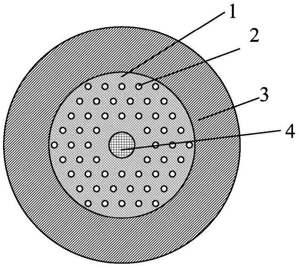
[0051] figure 1 A schematic cross-sectional view of one embodiment of the invention is given. The matrix material 1 is pure quartz, the refractive index difference between the high refractive index medium column 2 and the matrix material 1 is 0.029, and the refractive index difference between the high refractive index medium ring 3 and the matrix material 1 is 0.01. The refractive index difference between the core 4 and the matrix material 1 is 0.0075. The period of the high refractive index dielectric column 2 is 7.75 μm, and the core diameter is 12 μm. The number of layers of the high-refractive-index dielectric pillar 2 is N=3.
[0052] Fundamental model (LP of above-mentioned embodiment 01 mode) and higher order mode (LP 11 mode) The mode field distribution of Figure 4 shown. It can be seen that the fundamental mode field is coupled to the area where the high refractive index dielectric pillars 2 are arranged, thereby forming a high leakage loss. The mode field dis...
Embodiment 2
[0060] also in accordance with figure 1 In the structure of an optical fiber embodiment given, the matrix material 1 is pure quartz, the refractive index difference between the high-refractive index dielectric column 2 and the matrix material 1 is 0.029, and the refractive index difference between the high-refractive index dielectric ring 3 and the matrix material 1 is 0.01. The refractive index difference between the core 4 and the matrix material 1 was changed to 0.0105. The period of the high refractive index dielectric column 2 is 7.75 μm, and the core diameter is 12 μm. The number of layers of the high-refractive-index dielectric pillar 2 is N=3. The core structure can support LP 01 、LP 11 、LP 21 、LP 02 Four modes.
[0061] Such as Figure 9 As shown, it is the leakage loss curve of the effective refractive index of the core mode and the core mode as a function of wavelength in embodiment 2; Figure 9 (a) is the supermode group interval formed by the effective re...
Embodiment 3
[0064] Figure 10 A schematic cross-sectional view of another embodiment of the invention is given. Its parameters are the same as those in Embodiment 2, except that the number of layers of high refractive index dielectric pillars 2 is N=4. This structure reduces the LP by increasing the number of high refractive index dielectric columns 21 、LP 02 Leakage loss for both modes. Such as Figure 11 Shown, is the leakage loss curve of the core mode in embodiment 3 as a function of wavelength; Wherein, H01 is LP 01 Die leakage loss curve; H11 is LP 11 Die leakage loss curve, H21 is LP 21 Die leakage loss curve; H02 is LP 02 Die leakage loss curve. LP 11 mode still has high leakage losses, while the LP 21 、LP 02 The losses in both modes are reduced. LP if required 11 The loss of the mode is greater than 20dB / m, and the condition of mode transmission is that the loss of other modes is less than 0.1dB / m, the working wavelength range of this fiber can reach more than 200nm....
PUM
 Abstract
Description
Claims
Application Information
 - R&D
- Intellectual Property
- Life Sciences
- Materials
- Tech Scout
- Unparalleled Data Quality
- Higher Quality Content
- 60% Fewer Hallucinations
Browse by: Latest US Patents, China's latest patents, Technical Efficacy Thesaurus, Application Domain, Technology Topic, Popular Technical Reports.
© 2025 PatSnap. All rights reserved.Legal|Privacy policy|Modern Slavery Act Transparency Statement|Sitemap|About US| Contact US: help@patsnap.com


