Horn detector

A detector and horn technology, applied in the direction of electrical components, etc., can solve the problems of dangerous wires and inability to detect horns, etc., and achieve the effect of simple and convenient use, convenient hand-held portability, and adjustable output power

Inactive Publication Date: 2015-04-08
GUANGXI UNIV
View PDF5 Cites 1 Cited by
  • Summary
  • Abstract
  • Description
  • Claims
  • Application Information

AI Technical Summary

Problems solved by technology

[0004] The purpose of the present invention is to provide a tester for the horn, so as to overcome the defect that t

Method used


Image

  • Horn detector
  • Horn detector
  • Horn detector

Examples


Embodiment Construction

[0016] The specific embodiments of the present invention will be described in detail below in conjunction with the accompanying drawings, but it should be understood that the protection scope of the present invention is not limited by the specific embodiments.

[0017] Unless expressly stated otherwise, throughout the specification and claims, the term "comprise" or variations thereof such as "includes" or "includes" and the like will be understood to include the stated elements or constituents, and not Other elements or other components are not excluded.

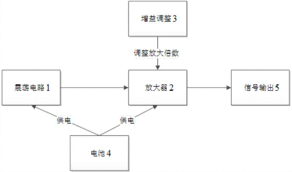
[0018] Such as figure 1 As shown, the speaker detector according to the specific embodiment of the present invention uses the bridge-type oscillating circuit 1 to generate an oscillating signal with a stable frequency, and the frequency of the oscillating signal is within the range of human hearing. Then the generated oscillating signal is amplified by the amplifier 2 to become an output signal with a certain output power....


PUM


Abstract

The invention discloses a horn detector. The horn detector comprises an oscillating circuit, an amplifier and two probes, wherein the oscillating circuit is fixed in a shell of the detector; the oscillating circuit is used for generating an oscillation signal with a stable frequency, and the frequency of the oscillating signal is within the hearing range of a person; the amplifier is fixed in the shell of the detector, and is used for amplifying the oscillation signal to form an output signal; the two probes are arranged on the shell; the two probes are connected with the two input ends of a horn respectively. The horn detector is small in size, is supplied with power through a battery, and is convenient to hold and carry; the gain of the amplifier is adjustable, so that the output power of the detector is adjustable; the probes can be detached, so that the horn detector is easy and convenient to use.

Description

technical field [0001] The invention relates to the field of electronic products, in particular to a horn detector. Background technique [0002] In the repair of electronic products or audio, it often involves the detection of the quality of the speakers. Many people choose to use live wires to touch. Good speakers often make a "beep" sound, but there is no It will not work in the case of electricity, and it is dangerous to use the wire directly. [0003] The information disclosed in this Background section is only for enhancing the understanding of the general background of the present invention and should not be taken as an acknowledgment or any form of suggestion that the information constitutes the prior art that is already known to those skilled in the art. Contents of the invention [0004] The object of the present invention is to provide a horn tester, so as to overcome the defects that the existing horn test method cannot test the horn without electricity, and i...

Claims


Application Information

Patent Timeline
IPC IPC(8): H04R29/00
Inventor 孙飞
Owner GUANGXI UNIV
Why Eureka
Try Eureka