
Flow control method and system for data link layer in mobile communication system

A mobile communication system and data link layer technology, applied in wireless communication, network traffic/resource management, electrical components, etc., can solve problems such as out-of-sync, decryption failure at the receiving end, low performance PDCP layer cache, etc.

Active Publication Date: 2018-08-10
WUHAN HONGXIN TELECOMM TECH CO LTD
View PDF5 Cites 1 Cited by
  • Summary
  • Abstract
  • Description
  • Claims
  • Application Information

AI Technical Summary

Problems solved by technology

[0005] 1. From a global perspective, the low performance of the eNB causes too much cache in the L2 data link layer (it may be too much cache in the PDCP layer or too much cache in the RLC layer), which in turn leads to memory exhaustion
[0006] 2. From the perspective of a certain UE (User Equipment, terminal user), when air interface encryption is enabled, if there are too many PDCP PDUs (Packet Data Unit, packet data unit) discarded continuously on an RB, exceeding the threshold, it will cause UE The HFN (Hyper-Frame Number, super-frame number) between the eNB and the eNB is out of sync, causing the receiver to fail to decrypt
For real-time services with high real-time requirements, the ARQ mechanism has a certain negative impact on the delay and the use of air interface resources.
[0010] To sum up, there is currently no flow control scheme that is more suitable for the data link layer of the mobile communication system, so that the mobile communication system can efficiently and reasonably perform flow control on the data link

Method used


Image

  • Flow control method and system for data link layer in mobile communication system
  • Flow control method and system for data link layer in mobile communication system
  • Flow control method and system for data link layer in mobile communication system

Examples


Embodiment Construction

[0076] The technical solution of the present invention will be described in detail below in conjunction with the accompanying drawings and embodiments.

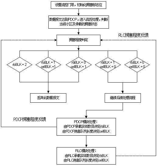
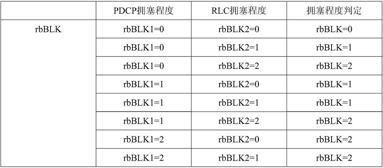
[0077] The present invention provides a flow control implementation scheme suitable for the data link layer of the LTE system. The basic design idea is: set the congestion flag bits at all levels to indicate the corresponding buffer occupancy (which can be reflected by the number of entities), and then the PDCP layer acts as a flow control The executor of the measures judges the congestion status of each PDCP SDU coming down: if it is in the congestion status, discard the SDU; otherwise, continue the subsequent processing flow. The subsequent PDCP layer and RLC layer, as the decision makers of the flow control measures, update the RB and CELL level congestion flags according to the number of entities in the current downlink buffer and the length of the downlink message queue.

[0078] For specific implementation, refer to the...


PUM


Abstract

The invention provides a flow control method and system for a data link layer in a mobile communication system. The flow control method comprises the following steps: initializing flow control threshold values, comprising a cell-grade flow control threshold value and a bearing-grade flow control threshold value of a PDCP layer and an RLC layer,; when a data message from a GTPU layer is received, judging a load condition of a base station by the PDCP layer according to a current congestion zone bit and processing the load condition; carrying out PDCP downstream flow processing; meanwhile, and carrying out pre-judgment on the cell-grade and bearing-grade congestion zone bits by the PDCT layer according to the length of a current downstream message queue and entity quantity downstream buffering zones; carrying out RLC downstream flow processing; meanwhile, and carrying out pre-judgment on the cell-grade and bearing-grade congestion zone bits by the RLC layer according to the length of a current downstream message queue and entity quantity of downstream buffering zones; utilizing pre-judgment results for flow control processing of subsequent new data messages. The flow control method and system in the technical scheme can be used for flow control on a data link efficiently and reasonably and ensure the stability of a base station system.

Description

technical field [0001] The present invention relates to the field of mobile communication technologies, in particular to a flow control technology for PDCP (packet data convergence protocol sublayer in the data link layer) in mobile communication systems (including but not limited to TDD-LTE, FDD-LTE) plan. Background technique [0002] In the existing mobile communication system, a three-layer wireless interface protocol system is usually adopted: a physical layer (L1), a data link layer (L2), and a network layer (L3). The data link layer can be further divided into MAC (Medium Access Control, Media Access Control) sublayer, RLC (Radio Link Control, Radio Link Control) sublayer and PDCP (Packet Data Convergence Protocol, packet data convergence protocol) sublayer . [0003] The lower layer of the PDCP sublayer is the RLC sublayer, the upper layer corresponding to the control plane is the RRC (Radio Resource Control, radio resource control) layer, and the upper layer corre...

Claims


Application Information

Patent Timeline
Patent Type & Authority Patents(China)
IPC IPC(8): H04W28/12
CPCH04W28/12
Inventor 徐海鑫张利达王方胡均武程潮李宗霖
Owner WUHAN HONGXIN TELECOMM TECH CO LTD
Learn More