Joint structure for steel-pipe pile, and steel-pipe pile

A steel pipe pile and structure technology, applied in sheet pile wall, foundation structure engineering, construction and other directions, can solve the problems of increased rotation time and labor, increased construction cost, etc., to avoid the increase of plate thickness, avoid processing cost, Avoiding the effect of increased material costs

Inactive Publication Date: 2015-04-08
NIPPON STEEL CORP
View PDF9 Cites 14 Cited by
  • Summary
  • Abstract
  • Description
  • Claims
  • Application Information

AI Technical Summary

Problems solved by technology

Therefore, there is a problem that the construction cost increases due to the increased labor required for the rotation time

Method used


Image

  • Joint structure for steel-pipe pile, and steel-pipe pile
  • Joint structure for steel-pipe pile, and steel-pipe pile
  • Joint structure for steel-pipe pile, and steel-pipe pile

Examples


no. 1 approach

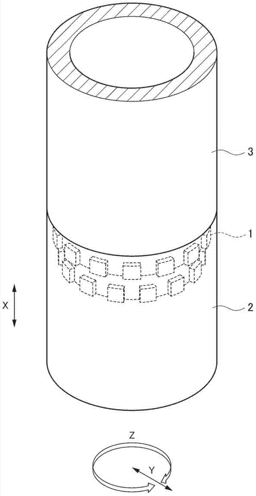
[0070] First, refer to figure 1 as well as figure 2 , the joint structure of the steel pipe pile according to the first embodiment of the present invention will be described. Such as figure 1 As shown, the joint structure 1 of the steel pipe pile according to the first embodiment is used to connect the lower steel pipe pile 2 (first steel pipe pile) and the upper steel pipe pile 3 (second steel pipe pile) in the axis direction X To connect (join).

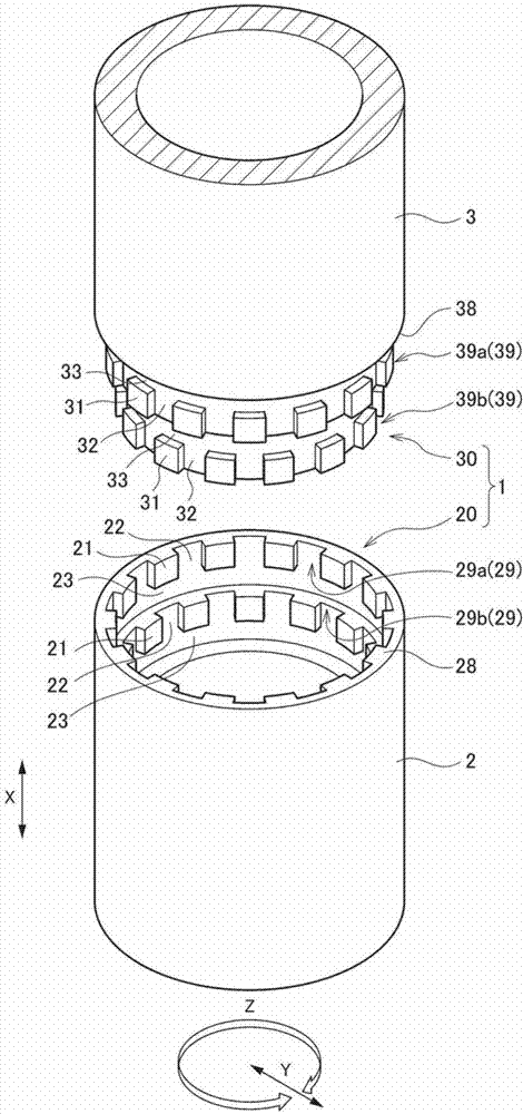
[0071] Such as figure 2 As shown, the joint structure 1 includes: an outer fitting end portion 20 provided at the upper end (open end) of the lower steel pipe pile 2; and a cylindrical inner fitting end portion provided at the lower end (one end) of the upper steel pipe pile 3 30. In the joint structure 1, the fitting end part 30 of the upper steel pipe pile 3 is fitted in the fitting end part 20 of the lower steel pipe pile 2 buried in the ground.

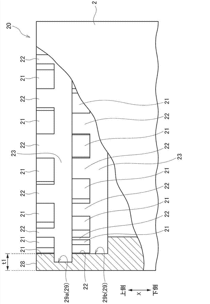
[0072] In the joint structure 1 of the first embodiment, two outer block p...


PUM


Abstract

This joint structure is a steel-pipe-pile joint structure for joining a first steel-pipe pile and a second steel-pipe pile to one another in series, and equipped with an outer-engaging-end part which is the opening end of the first steel-pipe pile, and a columnar inner-engaging-end part for forming a part to be inserted into the outer-engaging-end part and located at one end of the second steel-pipe pile, wherein: the outer-engaging-end part has a plurality of outer-engaging projections for projecting from the inner-circumferential surface thereof toward the inside in the radial direction, an outer-engaging groove part formed between the outer-engaging projections, and an outer-engaging coupling groove formed at a location toward the inside in the axial direction in relation to the outer-engaging projections and the outer-engaging groove; and the inner-engaging-end part has a plurality of inner-engaging projections projecting from the outer-circumferential surface thereof toward the outside in the radial direction.

Description

technical field [0001] The present invention relates to a joint structure of a steel pipe pile, and a steel pipe pile using the joint structure. combined, and the upper steel pipe pile and the lower steel pipe pile are connected along the axial core direction. More specifically, the present invention relates to a joint structure of steel pipe piles and steel pipe piles used in civil engineering fields such as building foundations and bridge foundations. [0002] This application claims priority based on Japanese Patent Application No. 2012-255304 for which it applied in Japan on November 21, 2012, and uses the content for this application. Background technique [0003] Conventionally, the joint structure of steel pipe piles aims to connect the upper steel pipe pile and the lower steel pipe pile along the axial direction, and they are roughly classified into screw type, key type, and gear type, and patent documents 1 to 3 have been proposed. The joint structure of such a st...

Claims


Application Information

Patent Timeline
Patent Type & Authority Applications(China)
IPC IPC(8): E02D5/24
CPCE02D5/24E02D5/285E02D5/526E02D2200/16E02D2600/20
Inventor 松宫弘信妙中真治津留英司藤井义法东壮哉坂井孝行望月惟史
Owner NIPPON STEEL CORP
Why Eureka
Try Eureka