Method of soldering iron tip with metal particle sintered member connected to heat conducting core

a technology of metal particle sintered member and soldering iron, which is applied in the direction of manufacturing tools, heating appliances, and solventing apparatus, etc., can solve the problems of reduced limited so as to reduce the working life of tips, and reduce the corrosion of soldering iron tips

Active Publication Date: 2009-02-17
HAKKO CO LTD
View PDF54 Cites 6 Cited by
  • Summary
  • Abstract
  • Description
  • Claims
  • Application Information

AI Technical Summary

Benefits of technology

[0009]“Soldering iron tip” as used in this disclosure refers to both the soldering iron tips of electrical soldering tools and soldering iron suction nozzles of desoldering tools. The Fe—Ni alloy plating described above provides some extension of the working life of the soldering iron tip. However, the working life of the tips is limited by the progressive loss of solder wettability; that is, the working life of soldering iron tips is limited by oxidation of the forward end thereof due to solder corrosion. The working life limit due to solder corrosion is the same as that for iron plated articles. For reasons such as the fact that the melting point of lead-free solder is higher than that of Sn—Pb solders, lead-free solders have greater corrosion of the soldering iron tip. Consequently, the working life of the tips is reduced due to the increased corrosion when lead-free solders are used. Increasing the thickness of the plating by increasing the length of the time during which the Fe—Ni alloy plating is performed disadvantageously further increases the plating processing time, which without the thicker plating takes twenty to thirty hours. In addition to the reduced productivity, increased cost can be expected due to the cost of processing environmental contaminants in the plating waste.

Problems solved by technology

However, the working life of the tips is limited by the progressive loss of solder wettability; that is, the working life of soldering iron tips is limited by oxidation of the forward end thereof due to solder corrosion.
Consequently, the working life of the tips is reduced due to the increased corrosion when lead-free solders are used.
Increasing the thickness of the plating by increasing the length of the time during which the Fe—Ni alloy plating is performed disadvantageously further increases the plating processing time, which without the thicker plating takes twenty to thirty hours.
In addition to the reduced productivity, increased cost can be expected due to the cost of processing environmental contaminants in the plating waste.
Although providing an Fe—Ni alloy coating member (bulk material) at the forward end of the soldering iron tip reduces corrosion, other problems result.
Consequently, problems arise when an Fe—Ni alloy coating member is provided at the forward end of a soldering iron tip since the characteristics thereof vary according to the type of solder used.
Selecting optimal physical characteristics to correspond to the type of solder used results in limited options and inability to achieve a satisfactory result.

Method used


Image

  • Method of soldering iron tip with metal particle sintered member connected to heat conducting core
  • Method of soldering iron tip with metal particle sintered member connected to heat conducting core
  • Method of soldering iron tip with metal particle sintered member connected to heat conducting core

Examples


Embodiment Construction

[0242]General Description of a Soldering Iron Tip

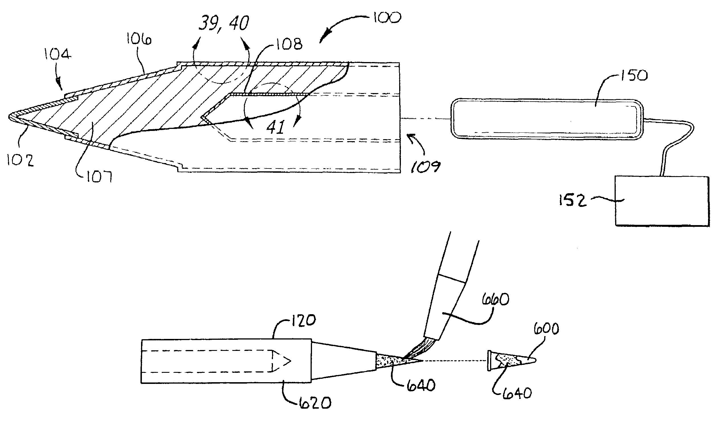
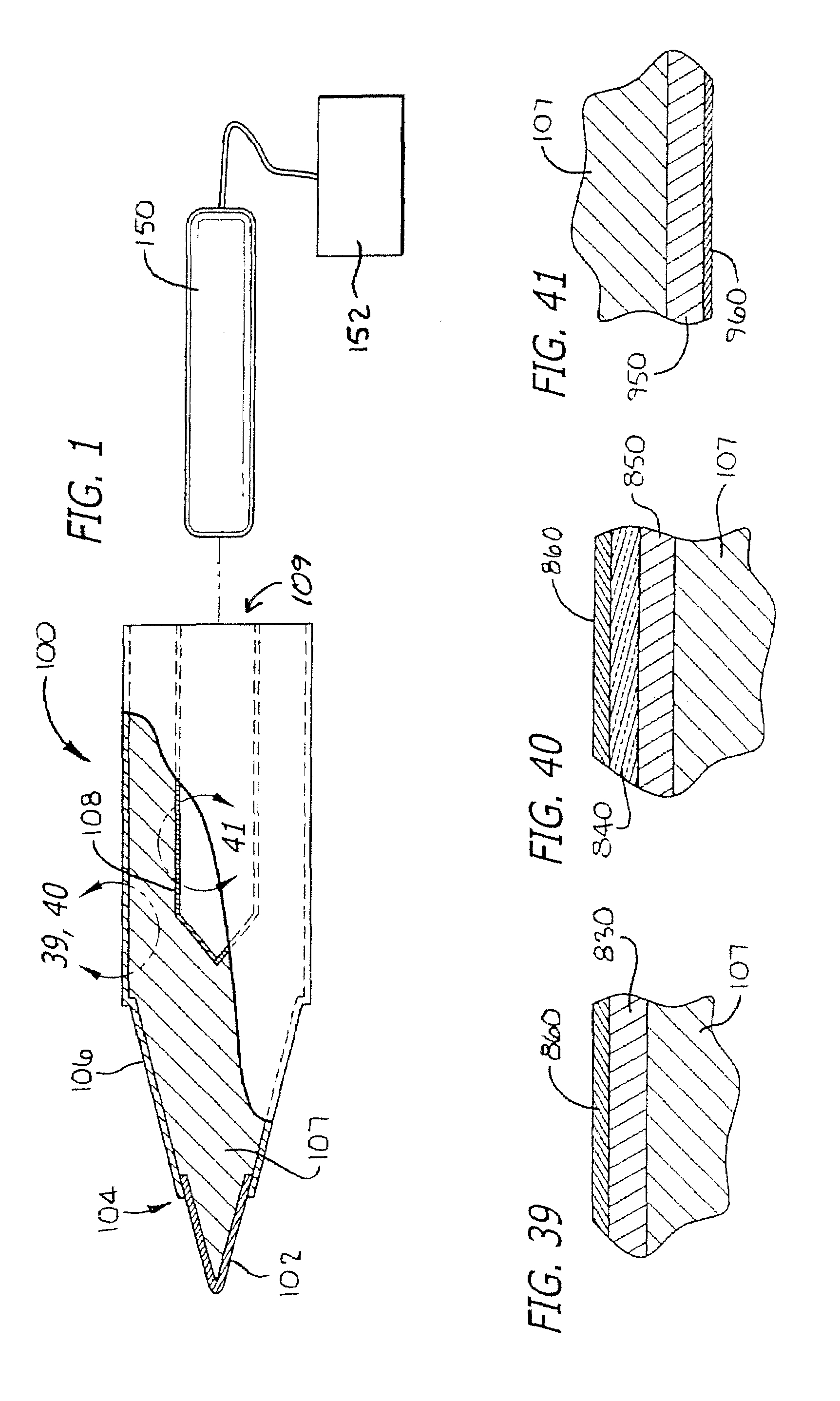
[0243]Referring to FIG. 1, a cross-sectional view of a preferred soldering iron tip of the present invention is illustrated generally at 100. Illustrated therein are four features, namely, the MIM cap 102, the joint 104 for the cap, the thermal spray coating 106 on the core 107, and the thermal barrier coating 108 in the cavity 109. Each of these will be described in greater detail and with other applications and alternatives in subsequent sections in this disclosure.

[0244]Advantages of the soldering iron tip 100 of FIG. 1 are that it is free of lead and chromium, can be used with lead-free solder, allows for the selection of various alternative materials (for longer life Fe-0.8C, for more wetness: Fe—Ag, Fe—Cu), better thermal conduction because the insert pipe has been removed, less error than caused by plating thickness, can be produced rather quickly so as to reduce stock (from forty-five days down to one day), and can be adapted ...


PUM

PropertyMeasurementUnit
sizeaaaaaaaaaa
sizeaaaaaaaaaa
temperatureaaaaaaaaaa

Abstract

A soldering iron tip having a copper or copper alloy core and a metal particle sintered member connected to the core to transfer heat therefrom to form a working soldering tip. The sintered member can be manufactured by powder metallurgy from a base material (iron, nickel and / or cobalt particles) and an additive (silicon, copper, silver, tin, boron and / or carbon particles) where needed. The sintered member can be formed as a cap which is fitted onto the working tip with a silver paste sandwiched therebetween, a brazing filler metal ring is positioned between an abutment shoulder and the cap, flux applied to the joint and the cap brazed into place. A metal, cermet or ceramic coating sprayed on the outer surface of the core, except for the (masked) working tip end, is not wettable by solder. An Ag—Al—Cu alloy coating layer in the rearwardly-disposed cavity improves heat conduction from the heater therein.

Description

[0001]This is a continuation of U.S. patent application Ser. No. 10 / 719,001, filed Nov. 21, 2003, now U.S. Pat. No. 7,030,339, the entire contents of which application are hereby incorporated by reference, and which claims priority to Japanese Patent No. 2002-342823, filed Nov. 26, 2002.BACKGROUND OF THE INVENTION[0002]The present invention relates to soldering iron tips for electric soldering tools and for desoldering tools. It further relates to methods of manufacturing soldering iron tips.[0003]Soldering is a method for connecting and bonding components and especially in the electronics industry. Soldering can be roughly classified into two categories, namely, mass soldering (batch soldering) and manual soldering. Mass soldering includes flow soldering mounting elements or components on a printed circuit board and then immersing the board in a molten solder bath. Mass soldering further includes reflow soldering (SMT) wherein soldered particles and flux are mixed with a binder or ...

Claims


Application Information

Patent Timeline
Patent Type & Authority Patents(United States)
IPC IPC(8): B23K3/02B22F7/06B22F7/08B23K3/03B23K35/30C22C38/00C22C38/08C22C38/10C22C38/16
CPCB22F7/064B22F7/08B23K3/025B23K3/0338C22C38/007C22C38/008C22C38/08C22C38/10C22C38/105C22C38/16B22F3/04B22F3/15B22F9/04B22F2998/00B22F2009/041B23K35/3006B23K2203/12B23K2103/12
Inventor NAGASE, TAKASHIUETANI, TAKASHITERAOKA, YOSHIMOTONAITO, TAKANORISEKIMORI, NORIHISAMIYABE, MASAYUKI
Owner HAKKO CO LTD
Why Eureka
Try Eureka