Drag chain with rollers

A chain and power technology, which is applied in the field of power guide chains, can solve the problems of uneconomical production and manufacturing costs of bottom parts, etc.

Inactive Publication Date: 2015-04-08
IGUS
View PDF10 Cites 6 Cited by
  • Summary
  • Abstract
  • Description
  • Claims
  • Application Information

AI Technical Summary

Problems solved by technology

However, this makes the production of the bottom part more complex and uneconomical in production, and the requ

Method used


Image

  • Drag chain with rollers
  • Drag chain with rollers

Examples


Embodiment Construction

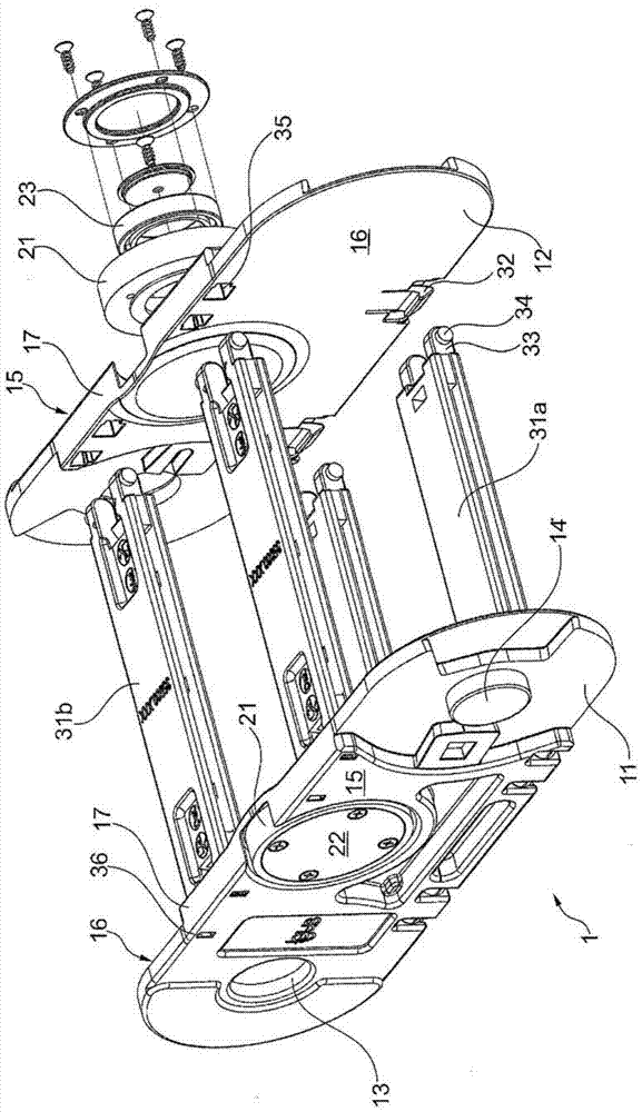
[0024] Figure 1 is a perspective view of a chain link 1 with features of the present invention. The chain link comprises two side plates 11, 12 which are mirror images of each other and have respectively a pivot sleeve 13 and a pivot journal 14 which are used during assembly. It is pivotally connected to the adjacent chain link. On the end with the pivoting sleeve 13 , the side plate 11 forms the outer surface 15 of the chain link 1 , while the inner surface 16 of the side plate 11 is exposed on the end with the pivot journal 14 .

[0025] The rollers 21 are recessed into the side plates 11 , 12 . The rollers are supported by ball bearings 23 on pivot journals 24 (not shown) and are protected by screwed covers 22 . When the chain is stretched out, the narrow faces 17 of the side plates 11, 12 form a continuous active surface on which the rollers 21 can roll.

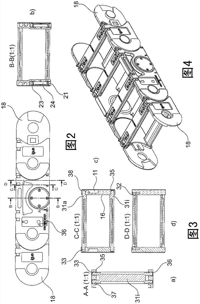
[0026] Located between the side plates are beams 31, in this case two inner beams 31i close to the active surface 1...


PUM


Abstract

On an energy guiding chain, for guiding hoses, cables and the like, with a number of chain links (1) connected to each other in articulated fashion, said links being formed by side straps (11, 12), which are parallel to each other and connected to form parallel side strap strands, and cross-members (31) connecting them, where the side straps can be pivoted relative to each other about a pivoting axis common to two adjacent side straps, where the energy guiding chain can be traversed in such a way that it forms a loop having an upper strand, a lower strand and a deflection zone connecting them, as a result of which an inner side and an outer side in relation to the loop is defined on the chain links, and where at least one end of the cross-members (31a) on the outer side of the chain links (1) can be detached from the side strap and pivoted in order to open the chain link (1), while the cross-members (31i) on the inner side of the chain links are permanently connected to the side straps, it is envisaged that rollers (21) be recessed into at least some side straps, said rollers projecting from the narrow face of the side straps and being able to roll on the narrow faces (17) of the side straps of the opposite strand during traversing of the chain, and that the permanent connection of the cross-members (31i) is made on the surfaces of the side straps facing towards the inside of the chain link.

Description

technical field [0001] The invention concerns a power guided chain according to the preambles of the independent claims. Background technique [0002] Such power guide chains are used for supplying and / or transmitting signals with a power carrier (such as electricity, water, gas, etc.) to consumers that are movable relative to a fixed connection point. Said power-guiding chain is assembled from a number of links pivotable relative to each other, said links comprising two opposite side plates and a beam connecting these side plates and accommodating within the space thus bounded Cables, hoses, etc. The space can be further divided by dividing webs between beams. In order to adapt the distance to the connection point during the movement of the consumer, the power guide chain forms a loop with an upper strand, a lower strand, and a flexure zone with a Radius of curvature limited by pivot angle. In this context, the upper strand can rest at least partially on the lower stran...

Claims


Application Information

Patent Timeline
IPC IPC(8): F16G13/16
CPCH02G11/006F16G13/16
Inventor T·A·耶克尔
Owner IGUS
Why Eureka
Try Eureka