
Fast engine block face milling fixture

A technology for engine cylinder block and end face milling, which is applied in the direction of clamping, manufacturing tools, metal processing machinery parts, etc., can solve the problems of low production efficiency of the end face of engine block, avoid the vibration of the workpiece under force, improve the processing quality, and improve the The effect of machining accuracy

Active Publication Date: 2017-02-22
重庆秦安机电股份有限公司
View PDF7 Cites 0 Cited by
  • Summary
  • Abstract
  • Description
  • Claims
  • Application Information

AI Technical Summary

Problems solved by technology

[0005] In view of this, the purpose of the present invention is to provide a fast engine block end face milling fixture to solve the problem of low production efficiency of using manual tooling to process the end face of the engine block

Method used


Image

  • Fast engine block face milling fixture
  • Fast engine block face milling fixture
  • Fast engine block face milling fixture

Examples


Embodiment Construction

[0020] The present invention will be further described below in conjunction with the accompanying drawings and embodiments.

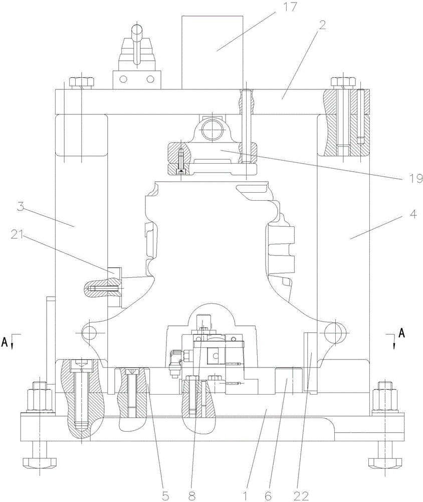
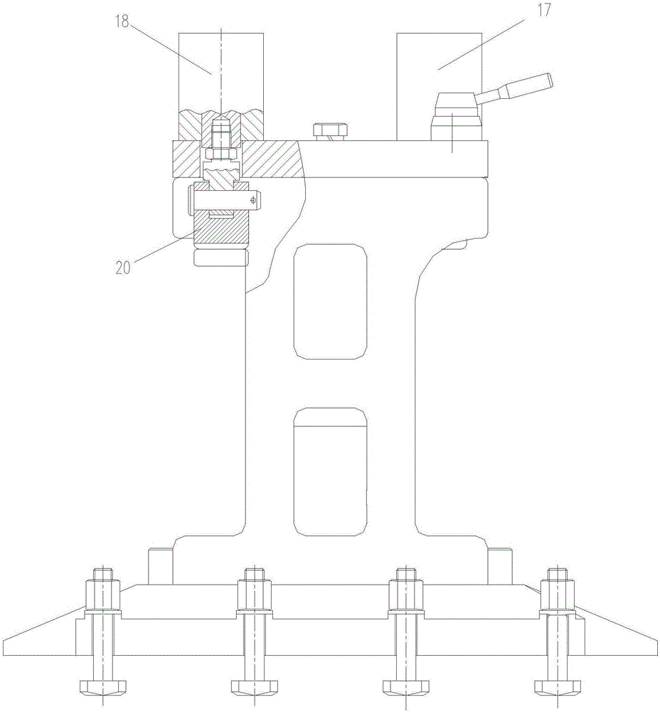
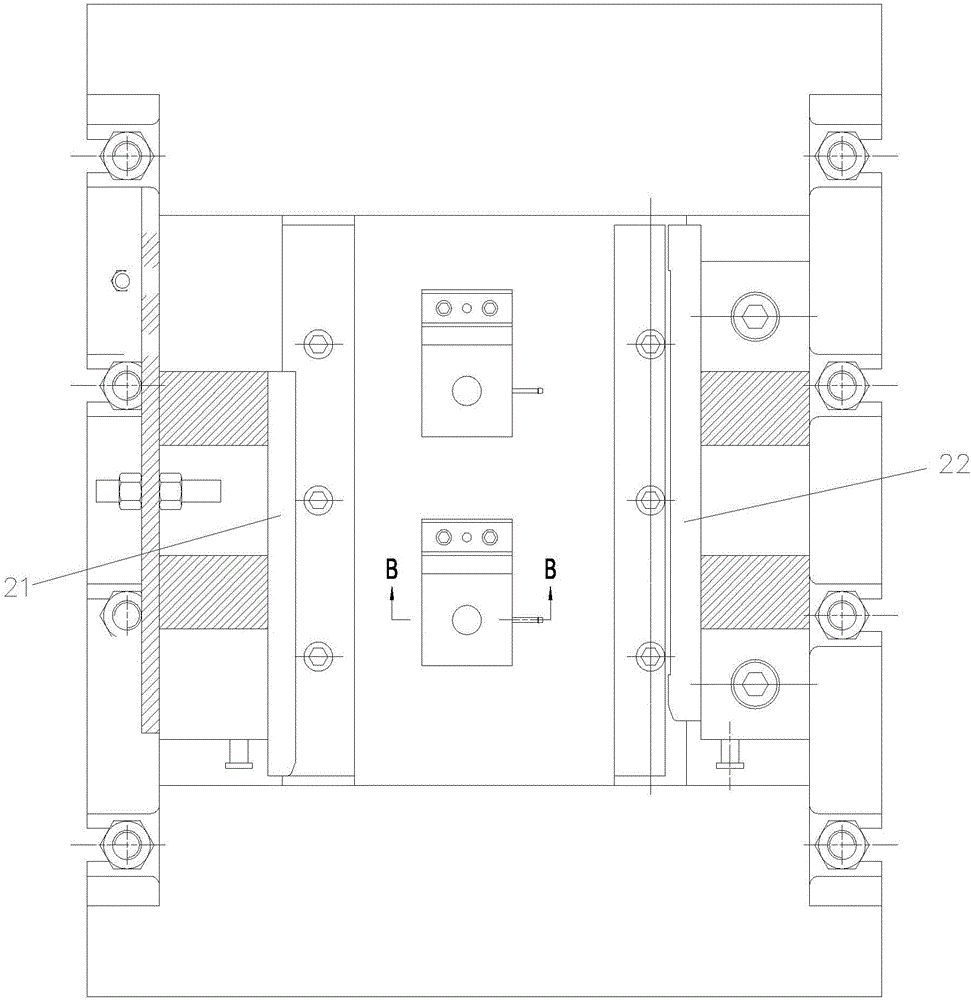
[0021] As shown in the figure, the quick-type engine block end face milling fixture of this embodiment includes a rectangular frame-shaped fixture body composed of a base 1, a top plate 2, a left vertical plate 3 and a right vertical plate 4, and the base is provided with a bar-shaped The left support block 5 and the strip-shaped right support plate 6, the base is also provided with two positioning pin devices that cooperate with the oil hole of the bearing seat hole on the engine block;

[0022] The positioning pin device includes a bottom plate 7 fixed on the base, an elastic positioning pin 8 and a support plate 9 fixedly arranged on the bottom plate; four axial opening grooves 10 are arranged on the positioning section of the elastic positioning pin along the circumferential direction Of course, the number of axial opening grooves can also be other ...


PUM


Abstract

The invention discloses a quick engine cylinder body end face milling clamp which comprises a clamp body, a left supporting block, a strip-shaped right supporting plate and a positioning pin device. A first hydraulic cylinder, a second hydraulic cylinder, a first press plate and a second press plate are arranged on a top plate. When the quick engine cylinder body end face milling clamp is used, an elastic positioning pin is inserted into an oil hole formed in an engine cylinder body bearing seat hole portion through a lifting air cylinder, the outer diameter of the positioning section of the elastic positioning pin is expanded by driving a positioning push rod to rise through an ejecting-expansion air cylinder, the expanded positioning pin is tightly matched with a workpiece oil hole, accordingly assembly gap errors can be eliminated, machining accuracy is improved, and after machining is completed, the positioning pin can break away from a workpiece, and accordingly interference of the positioning pin to workpiece taking can be eliminated. In addition, the clamp body is of a rectangular frame structure, the clamp is good in rigidity, the problem that the workpiece is stressed and shakes in the machining process can be avoided, an engine cylinder body is clamped by using the hydraulic cylinders to drive the press plates, clamping work efficiency is high, and therefore the production efficiency can be remarkably improved by means of the clamp.

Description

technical field [0001] The invention relates to a tool, in particular to a tool for milling the end face of an engine cylinder body. Background technique [0002] In the prior art, manual tooling is generally used to fix the engine block when milling the end face of the engine block. Although the manual tooling is simple to manufacture and the price is cheap, the clamping needs to be done manually by the operator, and the work efficiency is low. for the needs of modern production. [0003] And the positioning pins used in manual tooling are fixed positioning pins. After the fixed positioning pins are installed on the tooling, their positions cannot be changed, and the size of the positioning pins cannot be changed. [0004] Since the positioning pin needs to be inserted into the positioning hole of the workpiece, there must be a gap between the fixed positioning pin and the positioning hole on the workpiece, but the gap will cause assembly errors and reduce the manufacturin...

Claims


Application Information

Patent Timeline
Patent Type & Authority Patents(China)
IPC IPC(8): B23Q3/08
CPCB23Q3/062B23Q3/082
Inventor 唐亚东
Owner 重庆秦安机电股份有限公司
Learn More