Optical receiver and optical transmission system

a technology applied in the field of optical receiver and optical transmission system, can solve the problems of the band-limiting filter imposes a band-limitation on the input optical signal, and achieve the effect of eliminating waveform distortion and inter-symbol interferen

Inactive Publication Date: 2005-05-19
MITSUBISHI ELECTRIC CORP
View PDF8 Cites 25 Cited by
  • Summary
  • Abstract
  • Description
  • Claims
  • Application Information

AI Technical Summary

Benefits of technology

[0014] According to the above aspect, the optical band-limiting filter is provided on an upstream side with respect to the opto-electric converter. The full width at half maximum of this optical band-limiting filter is set to be equivalent to or smaller than the bit rate frequency of the optical signal. The optical band-limiting filter imposes a band-limitation on the input optical signal. The opto-electric converter converts the optical signal output from the optical band-limiting filter into an electric signal, and the electric signal is input to the electric equalizer. The electric equalizer performs an equalization processing on a signal waveform of this electric signal. In a series of these processings, the optical band-limiting filter imposes the band-limitation on the signal in the optical region, so that the SNR can be improved. On the other hand, however, a waveform distortion and an inter-symbol interference occur. The waveform distortion and the inter-symbol interference can be eliminated by the equalization processing performed by the electric equalizer in the electric region.

Problems solved by technology

The optical band-limiting filter imposes a band-limitation on the input optical signal.
On the other hand, however, a waveform distortion and an inter-symbol interference occur.

Method used


Image

  • Optical receiver and optical transmission system
  • Optical receiver and optical transmission system
  • Optical receiver and optical transmission system

Examples


first embodiment

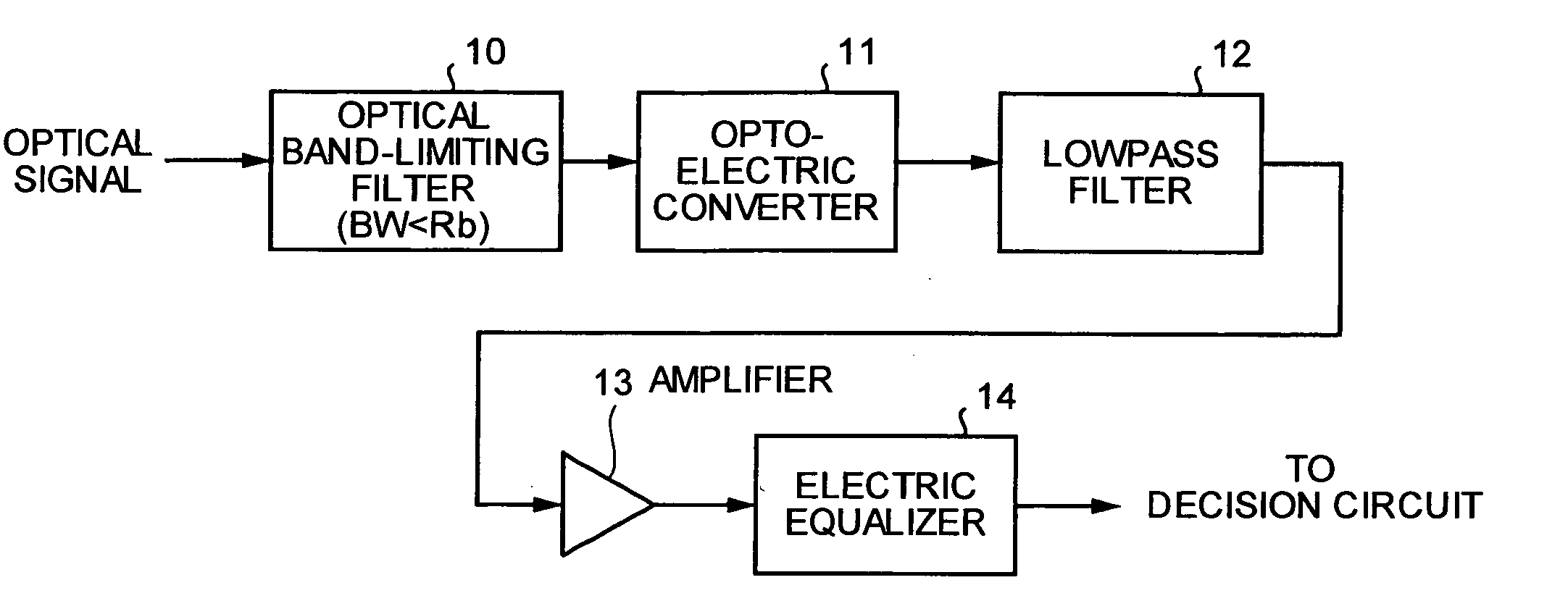
[0027]FIG. 1 is a block diagram which depicts a configuration of an optical receiver according to a first embodiment of the present invention. The optical receiver shown in FIG. 1 includes an optical band-limiting filter 10 into which an optical signal is input, an opto-electric converter 11 which receivers an output (the optical signal) of the optical band-limiting filter 10, a lowpass filter 12 which receives an output (an electric signal) of the opto-electric converter 11, an amplifier 13 which receives an output (the electric signal) of the lowpass filter 12, and an electric equalizer 14 which receives an output (the electric signal) of the amplifier 13.

[0028] An operation of the optical receiver will next be explained. In FIG. 1, the optical band-limiting filter 10 into which the transmitted optical signal is input imposes a band-limitation on a spectrum of the optical signal. The optical signal passed through the optical band-limiting filter 10 is converted into the electric ...

second embodiment

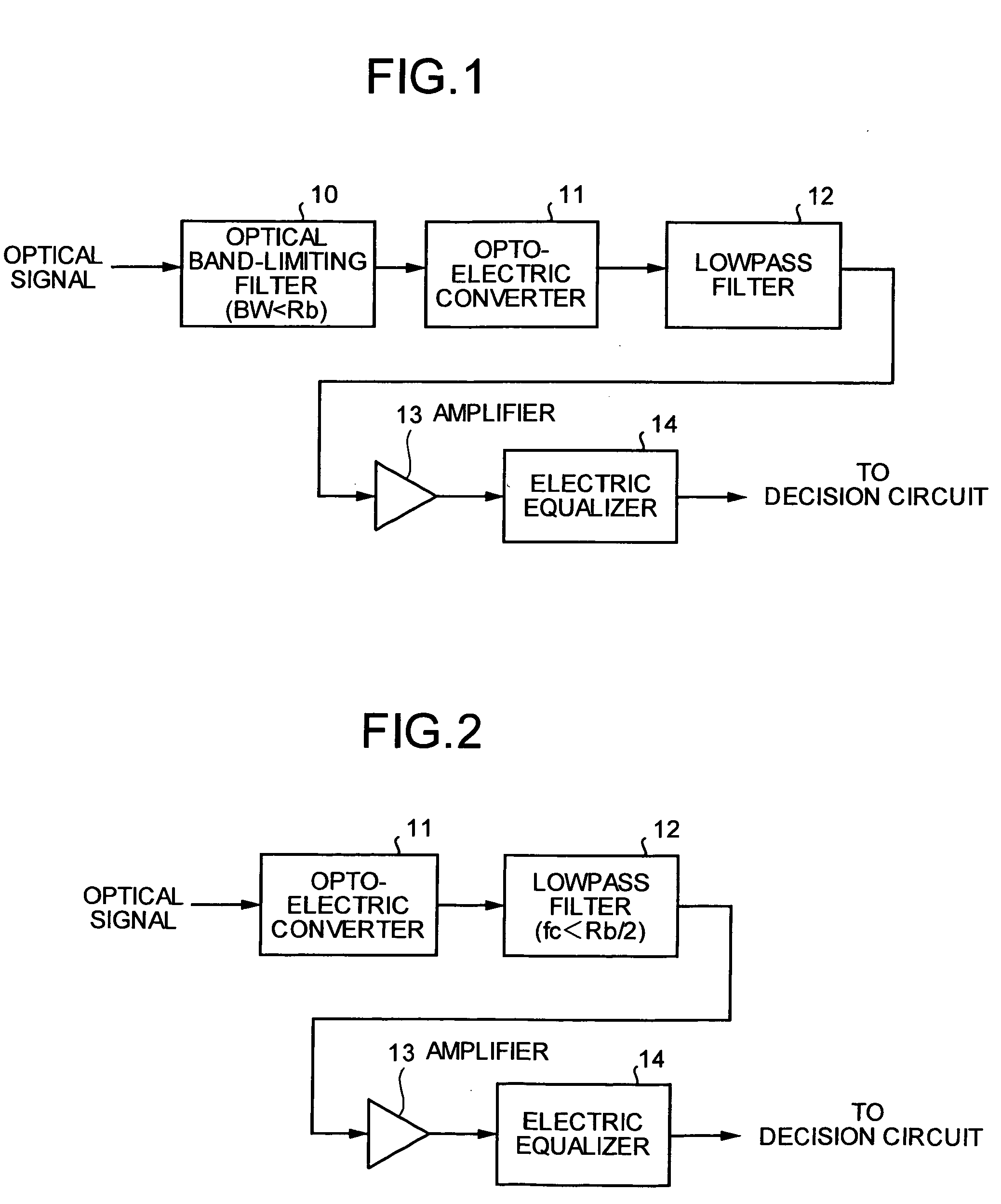
[0033]FIG. 2 is a block diagram which depicts a configuration of an optical receiver according to a second embodiment of the present invention. The optical receiver shown in FIG. 2 is constituted so that the optical band-limiting filter is removed from the configuration shown in FIG. 1. The other constituent elements of the optical receiver shown in FIG. 2 are equal or equivalent to those of the optical receiver shown in FIG. 1. Like constituent elements as those according to the first embodiment are designated by like reference signs, respectively.

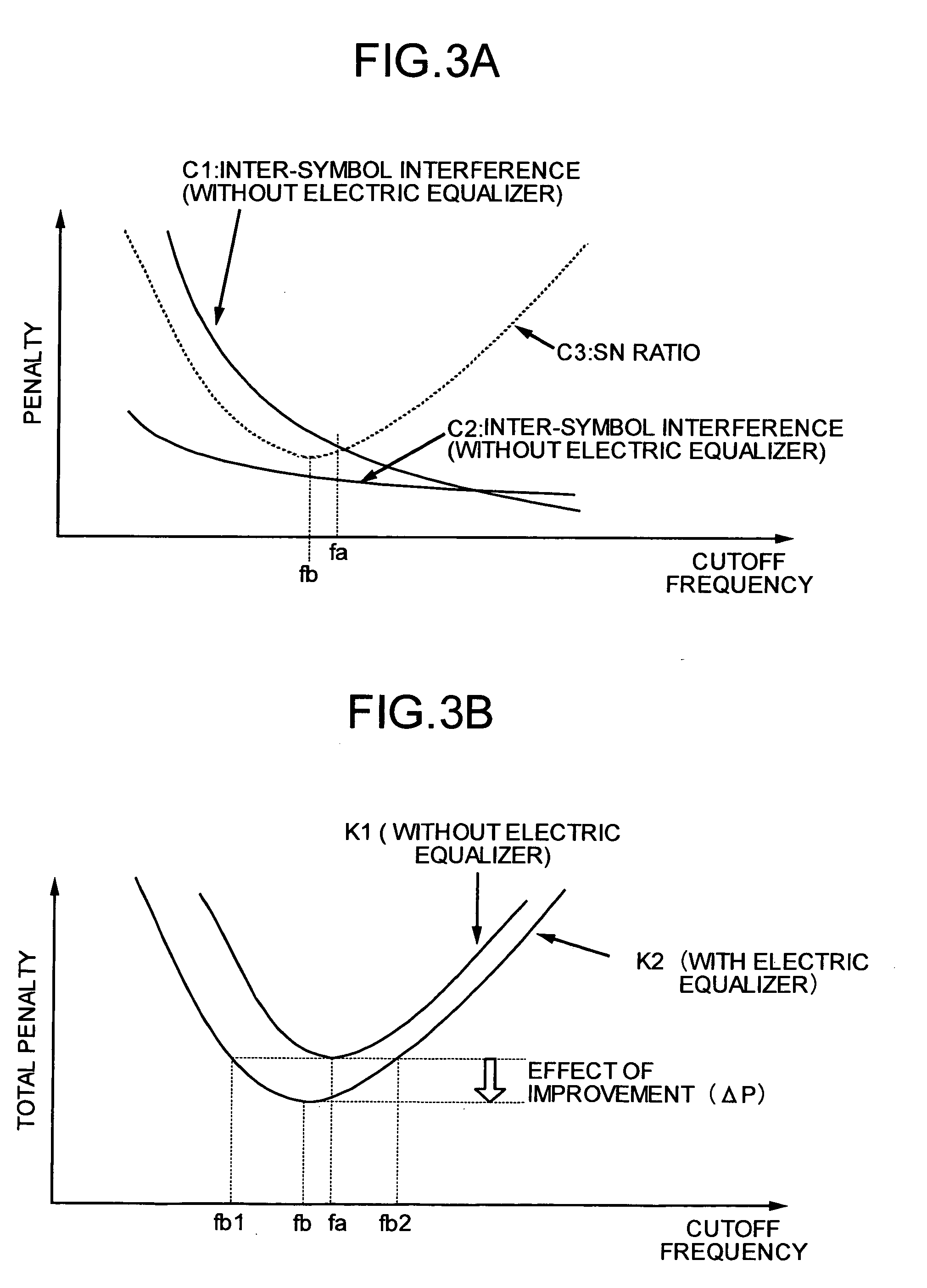
[0034] An operation of this optical receiver will next be explained with reference to FIGS. 2, 3A, and 3B. FIG. 3A is a graph of penalties when a cutoff frequency of the lowpass filter 12 is changed from viewpoints of the inter-symbol interference and a signal-to-noise ratio (SNR), respectively. FIG. 3B is a graph of a relationship between the cutoff frequency of the lowpass filter 12 and a total penalty of the inter-symbol interference ...

third embodiment

[0047]FIG. 4 is a block diagram which depicts a configuration of an optical receiver according to a third embodiment of the present invention. The optical receiver shown in FIG. 4 includes a decision circuit 15 that receives the output (the electric signal) of an electric equalizer 14 and a forward error correction code (FEC) decoder 16 that receives an output (the electric signal) of the decision circuit 15 in addition to the constituent elements shown in FIG. 1. The optical receiver shown in FIG. 4 also includes a control circuit 17 connected to the amplifier 13, the electric equalizer 14, and the decision circuit 15 by control signal lines.

[0048] An operation of this optical receiver will next be explained with reference to FIG. 4. Since the operation performed until the band-limited signal, the output level of which is adjusted by the electric equalizer 14, is output is the same as that according to the first embodiment, it will not be explained herein.

[0049] With reference to...


PUM


Abstract

The present invention includes an optical band-limiting filter which imposes a band-limitation on an input optical signal, an opto-electric converter which converts the optical signal output from the optical band-limiting filter into an electric signal, a lowpass filter which imposes the band-limitation on the electric signal output from the opto-electric converter, an amplifier which amplifies the output signal of the lowpass filter, and an electric equalizer which performs an equalization processing on a waveform of the electric signal output from the opto-electric converter are provided, and a full width at half maximum of the optical band-limiting filter is set to be equivalent to or smaller than a bit rate frequency of the optical signal.

Description

TECHNICAL FIELD [0001] The present invention relates to an optical receiver and an optical transmission system that includes an optical receiver. More specifically, the present invention relates to an optical receiver and an optical transmission system each of which holds high-quality, large-capacity, long-distance communications using an electric equalizer or the like. BACKGROUND ART [0002] An equalization technique for equalizing a waveform distortion using an electric circuit has been conventionally, actively utilized for high-quality data transmission in fields of wired communication using a metallic cable or the like and wireless communication. [0003] However, since application of the technique to optical communication has been confronted by various disadvantages, it has just been made practical. Specifically, as examples of the application of the electric equalizer to the optical communication system proposed so far, examples of a configuration of a feed-forward equalizer (FFE...

Claims


Application Information

Patent Timeline
Patent Type & Authority Applications(United States)
IPC IPC(8): H04B10/07H04B10/2507H04B10/40H04B10/50H04B10/524H04B10/556H04B10/60H04J14/00H04J14/02H04L1/00H04L25/03
CPCH04B10/675H04B10/6972H04B10/6971
Inventor SUGIHARA, TAKASHITOTSUKA, HIROFUMIMIZUOCHI, TAKASHI
Owner MITSUBISHI ELECTRIC CORP
Why Eureka
Try Eureka