Rising pipe arranged between steel ladle and vacuum chamber

A vacuum chamber and ladle technology, applied in the field of riser, can solve the problems of rotating jet energy attenuation, prolonging the smelting time, etc., and achieve the effect of large expansion angle, strong entrainment and mixing ability, and reduced splashing

Inactive Publication Date: 2015-04-15
BENGANG STEEL PLATES
View PDF5 Cites 0 Cited by
  • Summary
  • Abstract
  • Description
  • Claims
  • Application Information

AI Technical Summary

Problems solved by technology

[0005] The task of the present invention is to provide a riser arranged between the ladle and the vacuum chamber to solve the problems of the energy attenuation of the rotating jet in the molten steel and prolonging the smelting time by means of dislocation and rotating gas delivery.

Method used


Image

  • Rising pipe arranged between steel ladle and vacuum chamber
  • Rising pipe arranged between steel ladle and vacuum chamber
  • Rising pipe arranged between steel ladle and vacuum chamber

Examples


Embodiment Construction

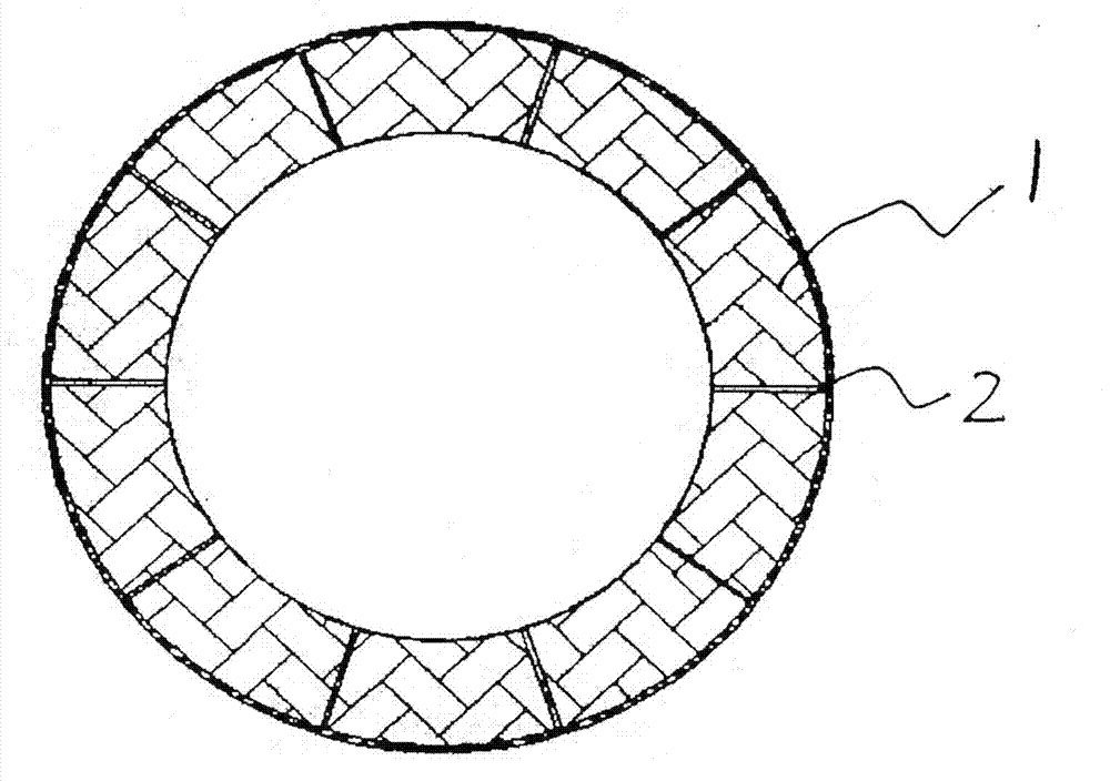
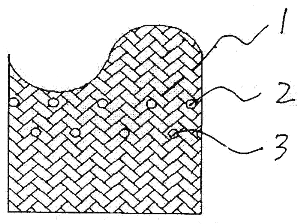
[0012] Such as Figure 1 to Figure 3 , these three drawings show the appearance structure schematic diagram of the rising tube arranged between the ladle and the vacuum chamber proposed by the present invention. The rising pipe is composed of a cylindrical hollow part 1, and the radial direction of the cylindrical hollow part 1 is provided with a first row of through holes 2 and a second row of through holes 3. The first row of through holes 2 proposed in this embodiment and the second row of through holes 3 are respectively provided with 10 through holes equidistantly spaced,

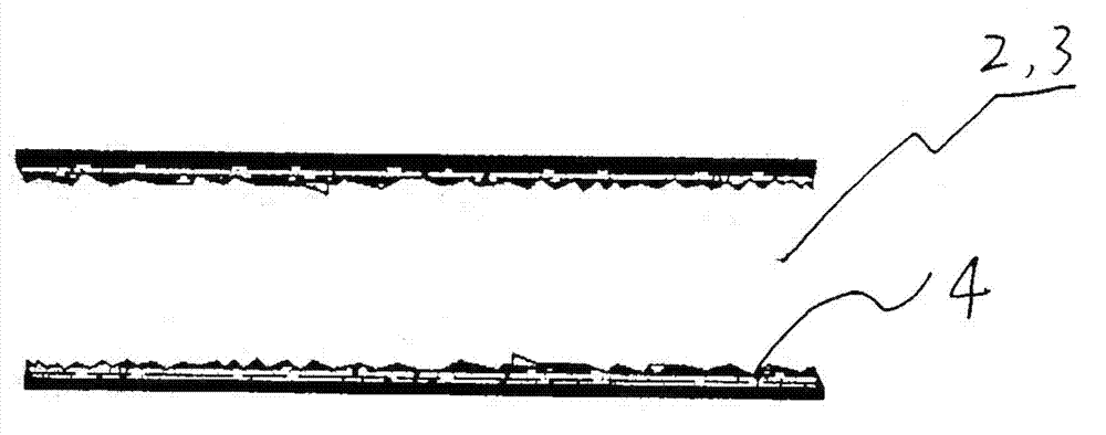
[0013] And the first row of through holes 2 and the second row of through holes 3 are misaligned up and down, that is, they are not on the same straight line in the axial direction, because the number of through holes can be determined according to the diameter of the cylindrical hollow part 1 , usually 8-13 through holes can be set; in addition, the inner surface of each through hole in the first row...


PUM

PropertyMeasurementUnit
diameteraaaaaaaaaa

Abstract

The invention relates to a rising pipe arranged between a steel ladle and a vacuum chamber. A first row of through holes and a second row of through holes which are axially staggered from the first row of through holes are radially formed in the rising pipe; threaded slots are formed in the inner surface of each through hole of the first row of through holes and the second row of through holes. In the arrangement way of the through holes of the rising pipe, energy loss caused by a gas jet into a central area of the rising pipe can be avoided, the utilization ratio of gas can be improved, and the circulating condition of molten steel is improved.

Description

technical field [0001] The invention relates to a riser arranged between a ladle and a vacuum chamber. Background technique [0002] The RH refining furnace is a vacuum cycle degassing equipment for molten steel. The RH refining furnace includes a ladle and a vacuum chamber arranged above the ladle, and a riser and a downcomer are installed between the ladle and the vacuum chamber. During the processing of molten steel in the RH refining furnace, because the ascending pipe is equipped with parts for blowing inert gas into it, the molten steel in the ladle is continuously input into the vacuum chamber through the ascending pipe, while the descending pipe is not provided for blowing inert gas. The gas component causes the molten steel entering the ladle to return to the ladle from the downcomer, so the circulating flow of molten steel between the ladle and the vacuum chamber is refined or alloyed. [0003] In the prior art, the riser of the RH refining furnace is usually prov...

Claims


Application Information

Patent Timeline
Patent Type & Authority Applications(China)
IPC IPC(8): C21C7/10C21C7/072
Inventor 陈立峰胡明谦赵庆玉李景宏耿雷
Owner BENGANG STEEL PLATES
Why Eureka
Try Eureka