Aero-engine labyrinth tight-sealing structure

A technology of aero-engine and sealing structure, applied in the direction of engine components, machines/engines, mechanical equipment, etc., can solve the problems of difficult to achieve circumferential blockage and small flow resistance.

Active Publication Date: 2015-04-15
南京亿贤奇信息科技有限公司
View PDF7 Cites 11 Cited by
  • Summary
  • Abstract
  • Description
  • Claims
  • Application Information

AI Technical Summary

Problems solved by technology

However, the traditional grate tooth seal structure is a smooth flow channel in the circumferential direction, and the flow resistance is small, so it is difficult to play the role of circumferential blocking

Method used


Image

  • Aero-engine labyrinth tight-sealing structure
  • Aero-engine labyrinth tight-sealing structure
  • Aero-engine labyrinth tight-sealing structure

Examples


Embodiment Construction

[0018] The present invention will be described in further detail below in conjunction with the accompanying drawings and specific embodiments.

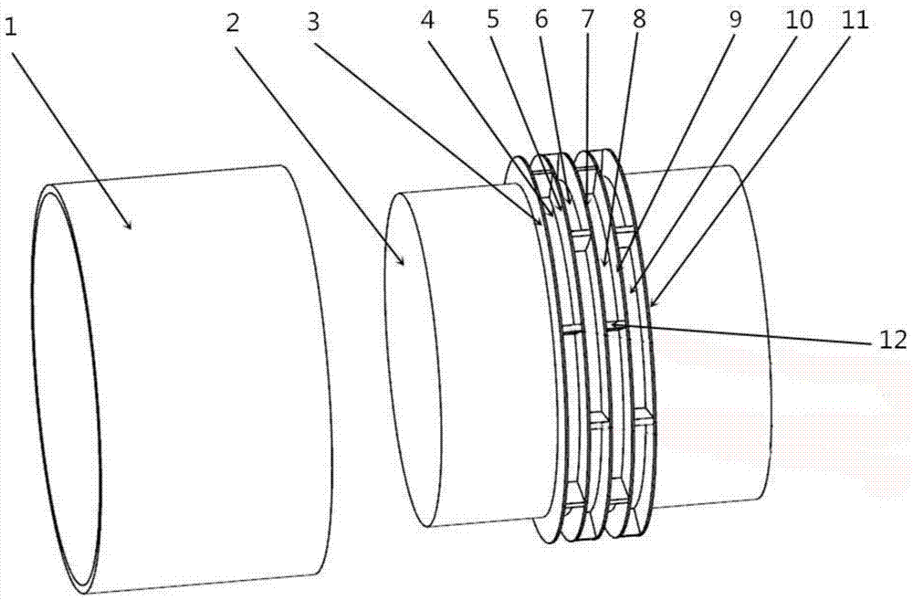
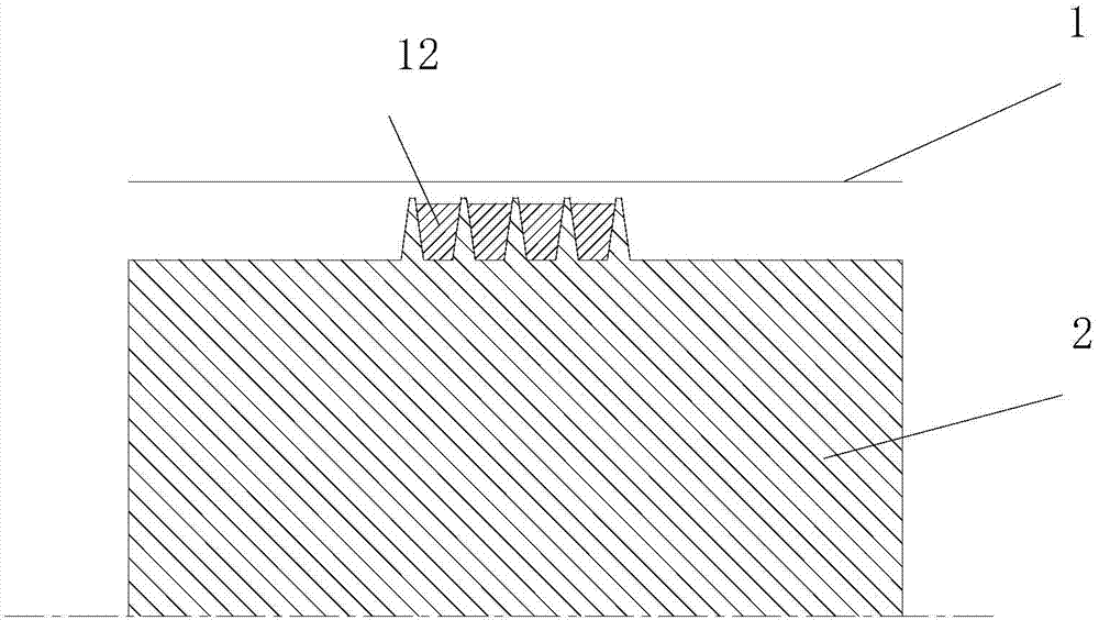
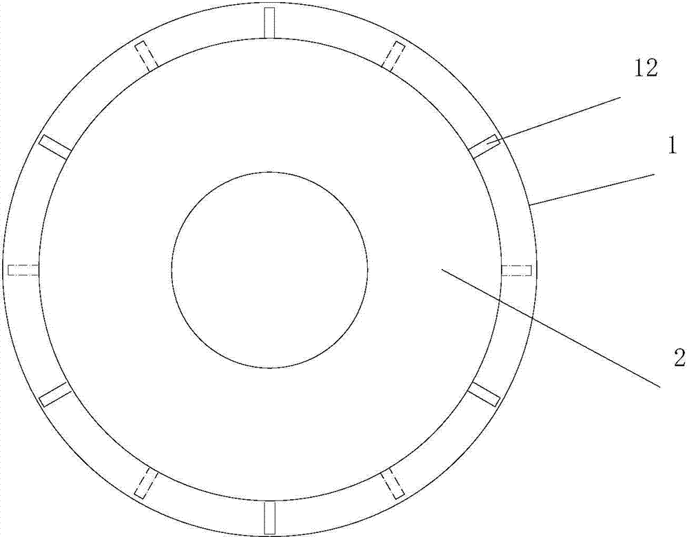
[0019] The aero-engine grate sealing structure as shown in the figure includes a sealing bush 1 and a rotating shaft 2. There are 5 stages of grating teeth on the rotating shaft 2, the first-stage grate teeth are 3, the second-stage grate teeth are 5, and the third-stage grate teeth 7. Four-stage grate teeth 9, five-stage grate teeth 11; grate tooth chambers are formed between two adjacent grate teeth, the first grate tooth chamber 4, the second grate tooth chamber 6, the third grate tooth chamber 8, The fourth grate tooth cavity 10; the circumferential tooth cavity partitions 12 are arranged in the grate tooth cavity, distributed in a circular array with an interval of 60°, and the tooth cavity partitions 12 in two adjacent grate tooth cavities are distributed at an interval of 30°.

[0020] The tooth chamber partition 12 is parallel...


PUM


Abstract

Provided is a labyrinth tight-sealing structure for increasing inner peripheral resistance of an aero-engine labyrinth cavity. The total flow reducing purpose is achieved by decreasing peripheral flowing of air flows. According to the specific technical scheme, the aero-engine labyrinth tight-sealing structure comprises a tight-sealing lining, a rotary shaft and a plurality of labyrinths arranged on the peripheral surface of the rotary shaft, wherein a labyrinth cavity is formed between every two adjacent labyrinths, and the tight-sealing lining is installed on the rotary shaft through a labyrinth structure. The aero-engine labyrinth tight-sealing structure is characterized in that labyrinth cavity partition plates are distributed in the labyrinth cavities in the peripheral direction and divide smooth annular flowing channels of the labyrinth cavities to form continuous peripheral cavity regions. By utilizing the throttling effect of the partition plates and eddy inside the cavities, peripherally-flowing air flows can flow up and down, fluid flowing resistance can be increased, the peripheral flowing of the labyrinth cavities can be reduced, and fluid leakage amount can be reduced.

Description

technical field [0001] The invention relates to an engine grate tooth sealing structure. Background technique [0002] With the development of the aviation industry, the requirements for the maneuverability, reliability and economy of the aircraft are getting higher and higher, so it is urgent to improve the various components of the aero-engine to ensure the high-performance requirements of the engine. Low fuel consumption, high thrust ratio, high reliability and durability are the development trends of modern aviation gas turbine engines, but the temperature and pressure ratio inside the engine are gradually increasing, making the leakage of the internal flow system more and more serious, and the performance of the seal is directly It affects the performance of aero-engines such as fuel consumption rate, flight cost, and thrust-to-weight ratio. In order to reduce leakage loss and improve the overall performance of the engine, it is particularly important to improve the or...

Claims


Application Information

Patent Timeline
Patent Type & Authority Applications(China)
IPC IPC(8): F01D11/08
Inventor 张勃李文凯吉洪湖
Owner 南京亿贤奇信息科技有限公司
Why Eureka
Try Eureka