
Capacitive MEMS (micro-electromechanical system) pressure sensor

A pressure sensor, capacitive technology, applied in fluid pressure measurement using capacitance changes, fluid pressure measurement through electromagnetic components, fluid pressure measurement, etc., can solve the problem of degradation of dynamic response range of nonlinear devices, increase in cost, and increase in device size and other issues, to achieve the effect of flexible device size, flexible adjustment, and cost reduction

Active Publication Date: 2015-04-15
CSMC TECH FAB2 CO LTD
View PDF6 Cites 18 Cited by
  • Summary
  • Abstract
  • Description
  • Claims
  • Application Information

AI Technical Summary

Problems solved by technology

It can be seen that in order to improve the sensitivity of the traditional capacitive MEMS pressure sensor, it is realized by increasing the size of the detection film, reducing the thickness of the detection film and reducing the distance between the electrode plates, but this introduces nonlinearity and dynamic response of the device. Deterioration of range and other indicators; due to increased film size, further increase in device size and cost increase

Method used


Image

  • Capacitive MEMS (micro-electromechanical system) pressure sensor
  • Capacitive MEMS (micro-electromechanical system) pressure sensor
  • Capacitive MEMS (micro-electromechanical system) pressure sensor

Examples


Embodiment Construction

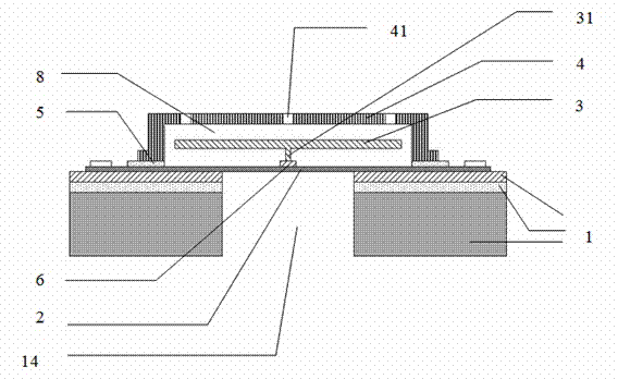
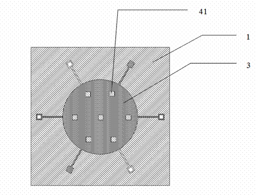
[0029] The present invention will be further described in detail below in conjunction with the accompanying drawings and embodiments. figure 1 A first embodiment of the invention is shown.

[0030] A capacitive MEMS pressure sensor is provided with:

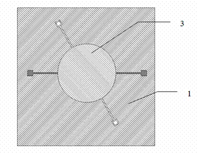
[0031] A substrate 1, a detection film 2, and a lower electrode plate 3 and an upper electrode plate 4 with lead wires.

[0032] The detection film 2 is fixedly laid on the upper surface of the substrate 1; the substrate 1 is provided with a through hole 14 (or any shape or groove) for the detection film 2 to be in contact with the external working medium and withstand its pressure;

[0033] The upper electrode plate 4 with lead wires is fixedly connected to the detection film 2 (it can also be fixed on the upper surface of the substrate 1, determined according to the size of the detection film 2 or the design and production process), and is located above the detection film 2 and connected to the detection film 2. A gap 8 is fo...


PUM


Abstract

A capacitive type MEMS pressure sensor, comprising a substrate (1), a detection thin film (2), an upper electrode plate (4) with a leading wire, and a lower electrode plate (3) with a leading wire. The detection thin film (2) is fixedly laid on an upper surface of the substrate (1). The upper electrode plate (4) is fixedly connected to the upper surface of the substrate (1) or the detection thin film (2). The upper electrode plate (4) is located above the detection thin film (2) and a gap (8) is formed between same and the detection thin film (2). The lower electrode plate (3) is fixedly arranged on the detection thin film (2). The lower electrode plate (3) is located in the gap (8) between the detection thin film (2) and the upper electrode plate (4). The lower electrode plate (3) and the upper electrode plate (4) constitute a capacitor. When a device is designed, the dimensions of the device can be more flexibly adjusted under specified device parameters so as to reduce costs. Moreover, the problem of changes in nonlinear and dynamic response ranges in the traditional pressure sensor is avoided in the structure of the device.

Description

technical field [0001] The invention relates to a pressure sensor, in particular to a capacitive MEMS pressure sensor. Background technique [0002] Capacitive pressure sensors are widely used due to their remarkable advantages such as low temperature drift, high sensitivity, low noise and large dynamic range. The contact capacitive pressure sensor is composed of a silicon diaphragm, a substrate, a substrate electrode and an insulating layer. A capacitive structure is formed between the silicon diaphragm and the substrate electrode; the silicon diaphragm is deformed after being subjected to pressure, and the electrode distance d changes accordingly. The MEMS capacitive pressure sensor includes two capacitors: one is the measurement capacitor C for measurement x , and the other is the reference capacitor C for temperature compensation o , when the diaphragm (upper electrode) is deformed when it is subjected to the pressure p, the distance between the diaphragm and the subs...

Claims


Application Information

Patent Timeline
IPC IPC(8): G01L9/12
CPCG01L9/0075
Inventor 夏长奉周国平钱栋彪
Owner CSMC TECH FAB2 CO LTD
Learn More