Image display method and electronic device

An electronic device and image display technology, applied in the field of electronics, can solve the problems of unable to display data display, visual fatigue, small display screen size, etc.

Inactive Publication Date: 2015-04-15
LENOVO (BEIJING) CO LTD
View PDF7 Cites 5 Cited by
  • Summary
  • Abstract
  • Description
  • Claims
  • Application Information

AI Technical Summary

Problems solved by technology

[0006] The embodiment of the present application provides an image display method and electronic equipment to solve the problem that the mobile phone in the prior art cannot clearly display th

Method used


Image

  • Image display method and electronic device
  • Image display method and electronic device
  • Image display method and electronic device

Examples


Embodiment 1

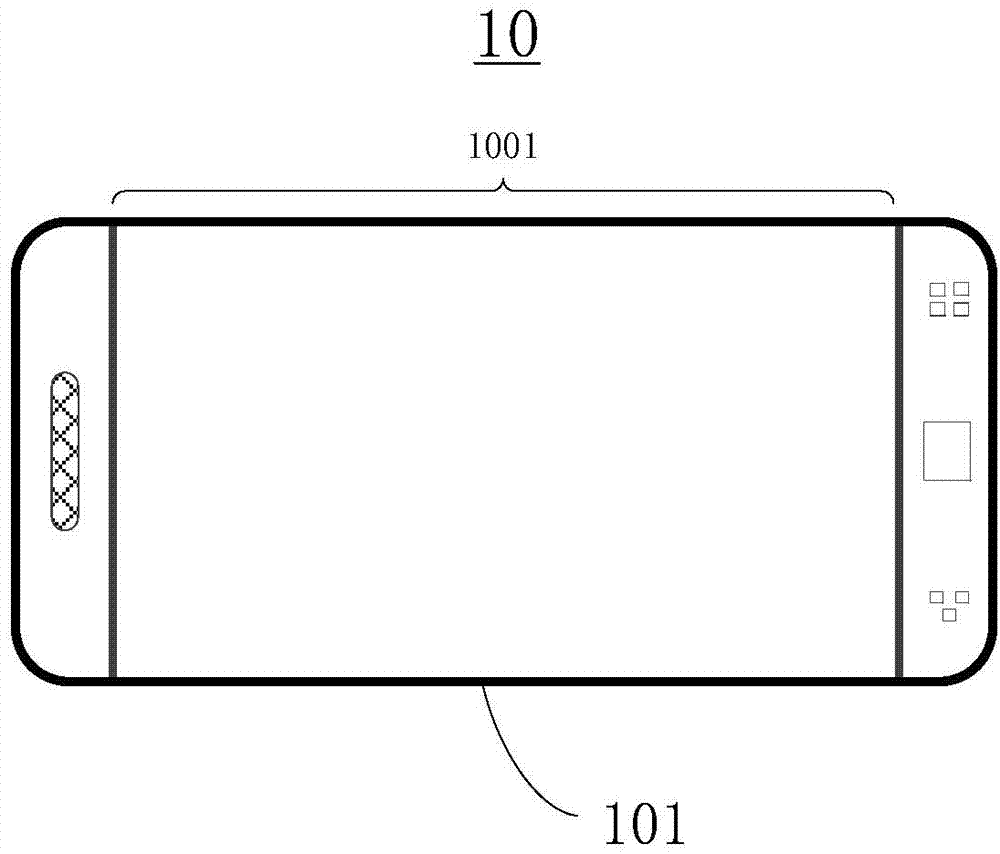
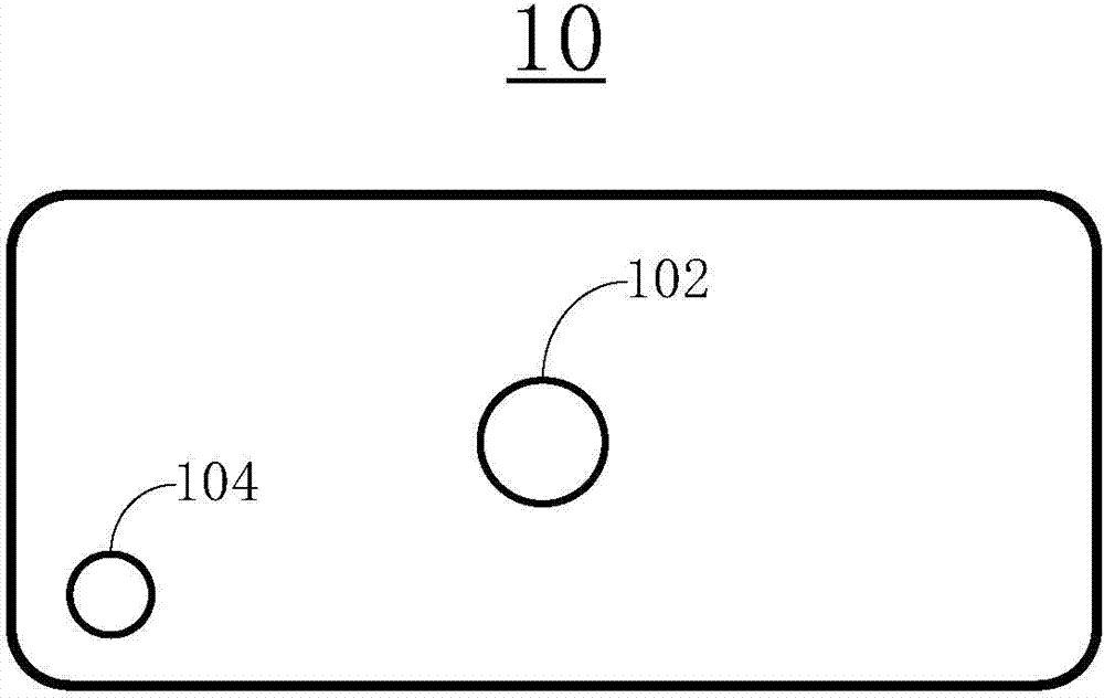
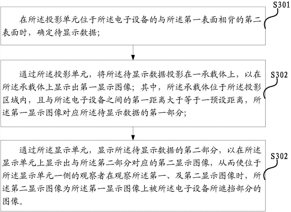
[0098] An image display method, such as figure 1 , figure 2 As shown, it is applied to an electronic device 10. In a specific implementation process, the electronic device 10 may be: a smart phone, a tablet computer, etc., for the specific electronic device 10, the embodiment of this application does not Make specific restrictions. The electronic device 10 includes a display unit 101 and a projection unit 102 having a projection area, wherein the display unit 101 is located on a first surface (usually referred to as the front side) of the electronic device 10, and the projection The unit 102 may be fixed on the second surface (usually called: the back) of the electronic device 10, and the first surface is opposite to the second surface; the projection unit 102 may also be: a freely rotatable The device can be rotated on the first surface, or rotated on the second surface; such as image 3 As shown, the method includes:

[0099] Step S301: When the projection unit is located on...

Embodiment approach

[0107] Based on the image display method provided above, this application also provides the following specific implementations, and the following various implementations can be combined arbitrarily:

[0108] The first implementation:

[0109] Such as Figure 5 As shown, the first distance between the carrier 20 and the projection unit 102 is greater than or equal to a preset distance, so that the carrier area on the carrier 20 for presenting the first display image is larger than the The display area of ​​the display unit.

[0110] In the prior art, smart phones generally can only use their own display unit for image display, but the size of this display unit is relatively small, so the image cannot be clearly displayed. It is easy for users to watch the image on the small screen for a long time. Visual fatigue occurs, and small-screen phones do not use to share images.

[0111] However, in this embodiment, the projection unit 102 is used to project the data to be displayed on the ca...

Embodiment 2

[0170] Based on the same inventive concept, another embodiment of the present application provides an electronic device that implements the image display method described in the embodiment of the present application.

[0171] Such as Figure 19 As shown, an electronic device includes:

[0172] A display unit 101 (such as a capacitive or resistive touch screen) located on the first surface of the electronic device 10;

[0173] A projection unit 102 (such as a projector) located on the second surface of the electronic device 10, the first surface is opposite to the second surface, and the projection unit 102 has a projection area;

[0174] A processor 103 is connected to the display unit 101 and the projection unit 102, and is configured to: when the projection unit 102 is located on the second surface of the electronic device opposite to the first surface, determine the Display data 40; through the projection unit 102, the to-be-displayed data 40 is projected on a carrier 20 to display...


PUM


Abstract

The present disclosure proposes an image displaying method applied in an electronic device. The electronic device comprises a display unit and a projection unit. The display unit is placed on a first surface of the electronic device. The method comprises: determining data to be displayed when the projection unit is placed on a second surface of the electronic device opposite to the first surface; projecting, by the projection unit, the data to be displayed onto a carrier to present a first display image on the carrier, the first display image corresponds to a first part of the data to be displayed; displaying, by the display unit, a second part of the data to be displayed to display a second display image corresponding to the second part on the display unit. The present disclosure further proposes an electronic device.

Description

Technical field [0001] The present invention relates to the field of electronic technology, in particular to an image display method and electronic equipment. Background technique [0002] With the development of technology, more and more electronic devices have entered people's lives, bringing many conveniences to people's lives. Among them, mobile phones have very powerful functions. They can make calls, send messages, play games, surf the Internet, stock stocks, etc. Mobile phones have become an indispensable tool in people's lives. [0003] In the prior art, mobile phones are equipped with a display screen for outputting text and image information to users. [0004] However, in the process of implementing the technical solutions of the invention in the embodiments of the present application, the inventor of the present application found that the above technology has at least the following technical problems: [0005] The display size of the mobile phone in the prior art is very s...

Claims


Application Information

Patent Timeline
IPC IPC(8): G06F3/14G06F3/0487G03B29/00
CPCH04N5/74A63F2300/105A63F2300/1075A63F2300/30A63F2300/301H04N9/3173H04N9/3185A63F13/211A63F13/213A63F13/2145A63F13/25A63F13/26A63F13/803
Inventor 邓袁圆
Owner LENOVO (BEIJING) CO LTD
Why Eureka
Try Eureka