Method and system for detecting QR (quick response) code correction graphics
一种校正图形、检测方法的技术,应用在机器使用的记录载体、电磁辐射感应、仪器等方向,能够解决无法快速准确的检测QR码校正图形等问题
- Summary
- Abstract
- Description
- Claims
- Application Information
AI Technical Summary
Problems solved by technology
Method used
Image
Examples
Embodiment 1
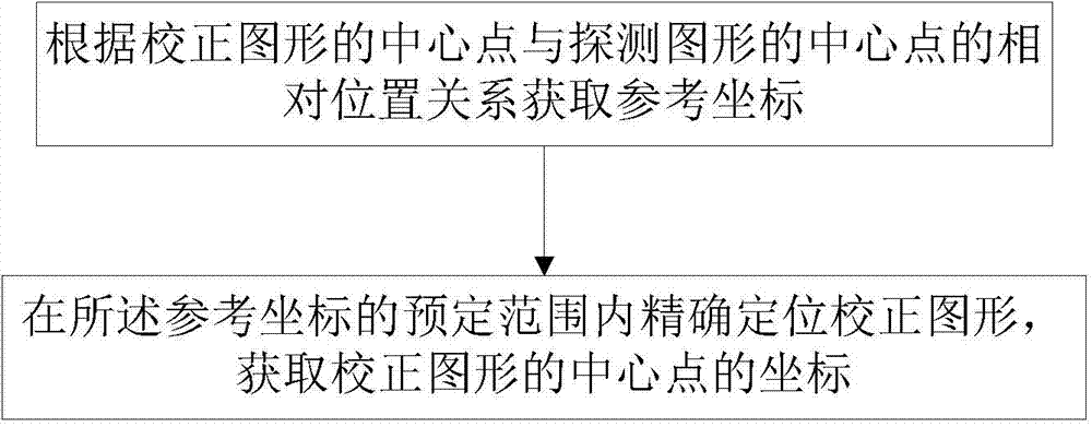
[0093]This embodiment provides a method for detecting QR code correction graphics, such as figure 1 shown, including the following steps:
[0094] Acquiring reference coordinates according to the relative positional relationship between the center point of the correction figure and the center point of the detection figure;
[0095] Accurately position the correction figure within the predetermined range of the reference coordinates, and obtain the coordinates of the center point of the correction figure.
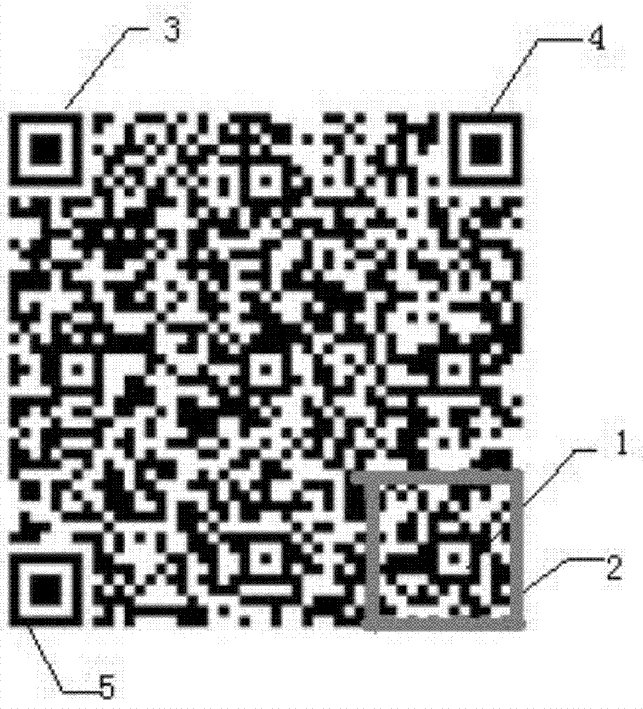
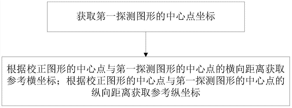
[0096] It should be noted that, depending on the version number of the QR code, the number and position of the correction graphics are different. In this embodiment, the detected and positioned correction pattern is the correction pattern in the lower right corner of the QR code, such as figure 2 The calibration graph shown in 1. Regardless of the version number, the correction graphic in the lower right corner is fixed to the edge of the QR code. Therefore, according t...
Embodiment 2
[0111] This embodiment is an improvement made on the basis of Embodiment 1. In the step of accurately locating the correction figure within a predetermined range of the reference coordinates and obtaining the coordinates of the center point of the correction figure, the predetermined range includes the reference coordinates square area. From figure 2 It can be seen from the figure that after the rough positioning of the correction figure is completed, a rough reference coordinate position is obtained, and then the correction figure is accurately positioned within the predetermined range of the reference coordinate, which is obviously located at the lower right corner of the QR image The correction graph of , falls in the square area, which is the gray line frame. If the square area is too large, the detection range will be too wide, and the calculation amount will be too large to make the detection speed slow. If the square area is too small, the correction pattern may not b...
Embodiment 3
[0131] This embodiment is an improvement made on the basis of Embodiments 1 and 2, and mainly detects some cases where the black module in the center of the correction pattern is severely distorted. At the same time, in order to fully consider various situations, in reality, the central black module will disappear due to distortion and other reasons, leaving only the white module, such as Figure 7 shown. For this situation, this embodiment also provides a corresponding detection method,
[0132] In the step of accurately positioning the correction figure within the predetermined range of the reference coordinates, and obtaining the coordinates of the center point of the correction figure:
[0133] If no horizontal or vertical line segment whose length ratio of white:black:white meets the preset ratio is detected after detecting the predetermined range along the first direction, the following steps are performed:
[0134] Detecting the predetermined range along the first dir...
PUM
 Abstract
Description
Claims
Application Information
 - R&D
- Intellectual Property
- Life Sciences
- Materials
- Tech Scout
- Unparalleled Data Quality
- Higher Quality Content
- 60% Fewer Hallucinations
Browse by: Latest US Patents, China's latest patents, Technical Efficacy Thesaurus, Application Domain, Technology Topic, Popular Technical Reports.
© 2025 PatSnap. All rights reserved.Legal|Privacy policy|Modern Slavery Act Transparency Statement|Sitemap|About US| Contact US: help@patsnap.com


