Equipment cabinet convenient for circuit arrangement

It is a circuit and convenient technology, which is applied in the direction of casing/cabinet/drawer parts, electrical equipment casing/cabinet/drawer, cooling/ventilation/heating transformation, etc. It can solve the problems of messy internal lines and inconvenient arrangement, and achieve The height and space size can be adjusted, the operation is convenient, and the finishing effect is effective

Inactive Publication Date: 2015-04-15
MIANYANG XINGDONG ELECTRONICS TECH
View PDF7 Cites 1 Cited by
  • Summary
  • Abstract
  • Description
  • Claims
  • Application Information

AI Technical Summary

Problems solved by technology

[0007] The purpose of the present invention is to solve the problem of inconvenient tidying due to messy internal lines when the existing cabinet is installed, and to provide a convenient line tidying type cabinet with adjustable distance between partitions in the cabinet and very convenient line tidying

Method used


Image

  • Equipment cabinet convenient for circuit arrangement
  • Equipment cabinet convenient for circuit arrangement
  • Equipment cabinet convenient for circuit arrangement

Examples


Embodiment 1

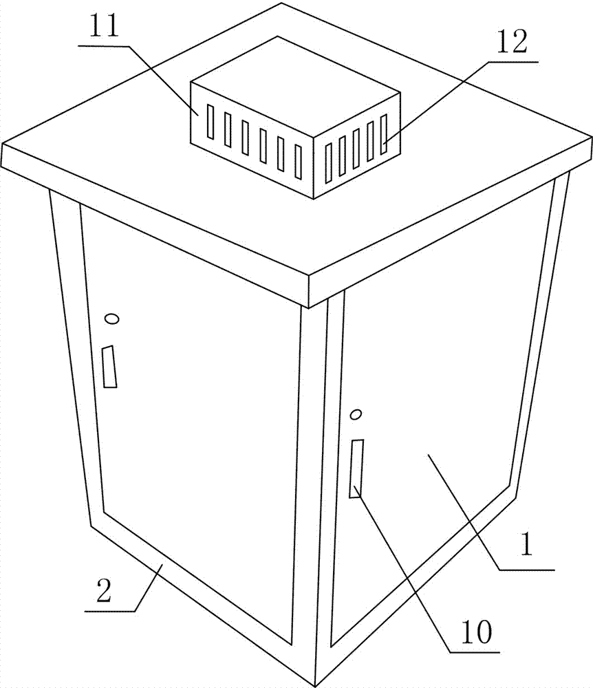
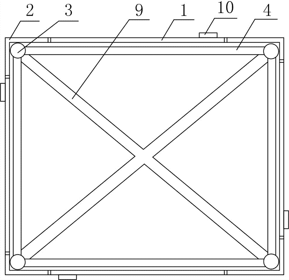
[0031] Convenient line management cabinets, such as Figure 1~4 As shown, it includes a casing 2 provided with cabinet doors 1 on four sides, a frame body arranged inside the casing 2 for supporting the casing 2, and a partition shelf set on the frame body, and placing A shelf on the shelf shelf.

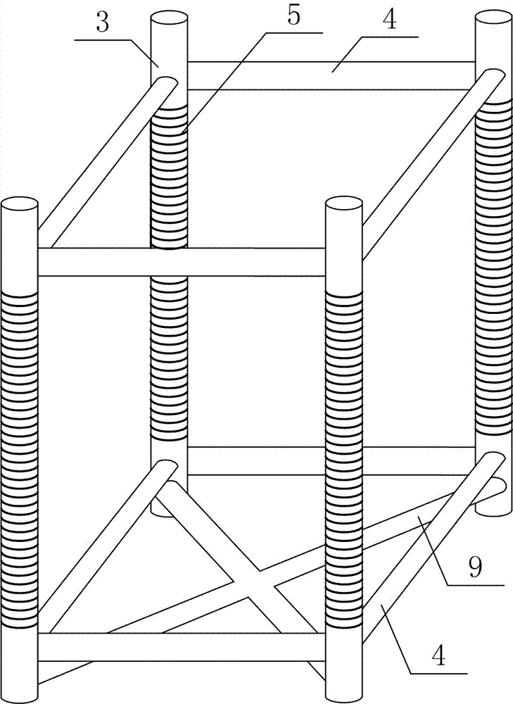
[0032] Wherein, the frame body consists of four columns 3 arranged in parallel and in a rectangular arrangement, connecting rods 4 arranged at the bottom and top of the columns 3 and connecting two adjacent columns 3 , and annular grooves arranged on the columns 3 5 composition.

[0033] The partition shelf is composed of a fastening piece 6 that is fastened on the column 3, a protruding piece 7 that is arranged on the inner surface of the fastening piece 6 and matches the annular groove 5, and a protrusion that is arranged on the fastening end of the fastening piece 6. Bolt fixing holes 8, as well as bolts and nuts that fix the fastener on the column 3 through the bolt fixing hol...

Embodiment 2

[0037] The difference between this embodiment and Embodiment 1 is that this embodiment optimizes the structure of the housing 2 and the frame, such as figure 1 and image 3 As shown, the specific setting method is as follows:

[0038] A cross connector 9 is provided at the bottom or / and top of the column 3 . In this embodiment, the cross connector 9 is only arranged at the bottom of the column 3 .

[0039] In order to facilitate opening and closing of the cabinet door 1 , a handle 10 is provided on the cabinet door 1 .

[0040] At the same time, in order to achieve a better heat dissipation effect, the top of the housing 2 is provided with a heat dissipation device, and the bottom end of the heat dissipation device communicates with the box body 11 inside the housing 2, and the heat dissipation air holes arranged on the side wall of the box body 11 12 compositions. An exhaust fan is also arranged inside the box body 11 .


PUM


Abstract

The invention discloses an equipment cabinet convenient for circuit arrangement, mainly solving the problem of inconvenience in arrangement during mounting of existing equipment cabinets due to disordered internal circuits. The equipment cabinet comprises a housing, a frame, separation plate holding pieces and separation plates. Cabinet doors are arranged on four side faces of the housing respectively. The frame arranged in the housing is used for supporting the housing. The separation plate holding pieces are arranged on the frame, and the separation plates are placed on the separation plate holding pieces. The frame comprises four parallel stand columns in rectangular arrangement, connecting rods and annular grooves, wherein the connecting rods are arranged at the bottom ends and the top ends of the stand columns and are connected with every two adjacent stand columns, and the annular grooves are formed in the stand columns. Each separation plate holding piece comprises a fastening piece, protrusion pieces, bolt fixing holes, a bolts and a nut, the fastening pieces are fastened to the stand columns, the protrusion pieces are arranged on the inner surfaces of the fastening pieces and are matched with the annular grooves, the bolt fixing holes are formed in the fastening ends of the fastening pieces, and the bolts and the nuts are used for fixing the fastening pieces to the stand columns through the bolt fixing holes. The equipment cabinet has the advantages of adjustability in gaps among the separation plates in the cabinet, convenience in circuit arrangement and the like.

Description

technical field [0001] The invention relates to a cabinet, in particular to a convenient line arrangement type cabinet. Background technique [0002] The cabinet is generally made of cold-rolled steel plate or alloy to store computers and related control equipment. It can provide protection for storage equipment, shield electromagnetic interference, and arrange equipment orderly and neatly to facilitate future maintenance of equipment. Cabinets are generally divided into server cabinets, network cabinets, console cabinets, etc. [0003] Most of the cabinets used in the early days were made of castings or angle steels connected or welded into the cabinet frame by screws, rivets, and then made of cover plates (doors) made of thin steel plates. This kind of cabinet has been eliminated due to its large volume, heavy weight and simple appearance. With the use of transistors and integrated circuits and the miniaturization of various components, the structure of the cabinet is al...

Claims


Application Information

Patent Timeline
Patent Type & Authority Applications(China)
IPC IPC(8): H05K5/00H05K5/02H05K7/20H05K7/14
Inventor 刘志东
Owner MIANYANG XINGDONG ELECTRONICS TECH
Why Eureka
Try Eureka