Filtering and pushing mechanism of extraction and filtration groove for product

A technology of pushing mechanism and suction filter tank, applied in fixed filter element filters, filtration separation, chemical instruments and methods, etc., can solve the problems of reducing the rate of filtration, inconvenient cleaning, and shortening the service life of the filter screen. Easy to install and use, ensure service life and good stability

Inactive Publication Date: 2015-04-22
CHONGQING JINSHAN GENERAL MACHINERY MFGCO
View PDF0 Cites 2 Cited by
  • Summary
  • Abstract
  • Description
  • Claims
  • Application Information

AI Technical Summary

Problems solved by technology

[0003] However, in the prior art, only the two ends of the filter screen are supported, which often cannot provide enough support for the filter screen, so that the service life of the filter screen is reduced; the parallel setting of the filter screen membrane will reduce the filtration rate, and for some The solvent exposed to the air for a long time will affect the chemical properties of the solvent; there is no space to gather solid substances, which is not convenient for the centralized treatment of solid substances; in addition, the filter screens are fixed in the suction filter, which is inconvenient to clean after use

Method used


Image

  • Filtering and pushing mechanism of extraction and filtration groove for product
  • Filtering and pushing mechanism of extraction and filtration groove for product
  • Filtering and pushing mechanism of extraction and filtration groove for product

Examples


Embodiment Construction

[0019] The specific implementation manner and working principle of the present invention will be further described in detail below in conjunction with the accompanying drawings.

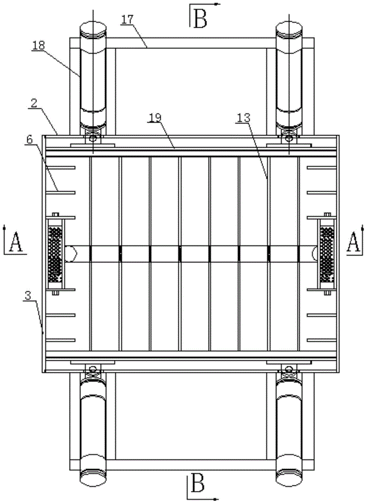
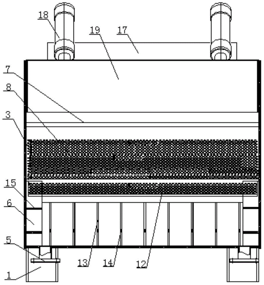
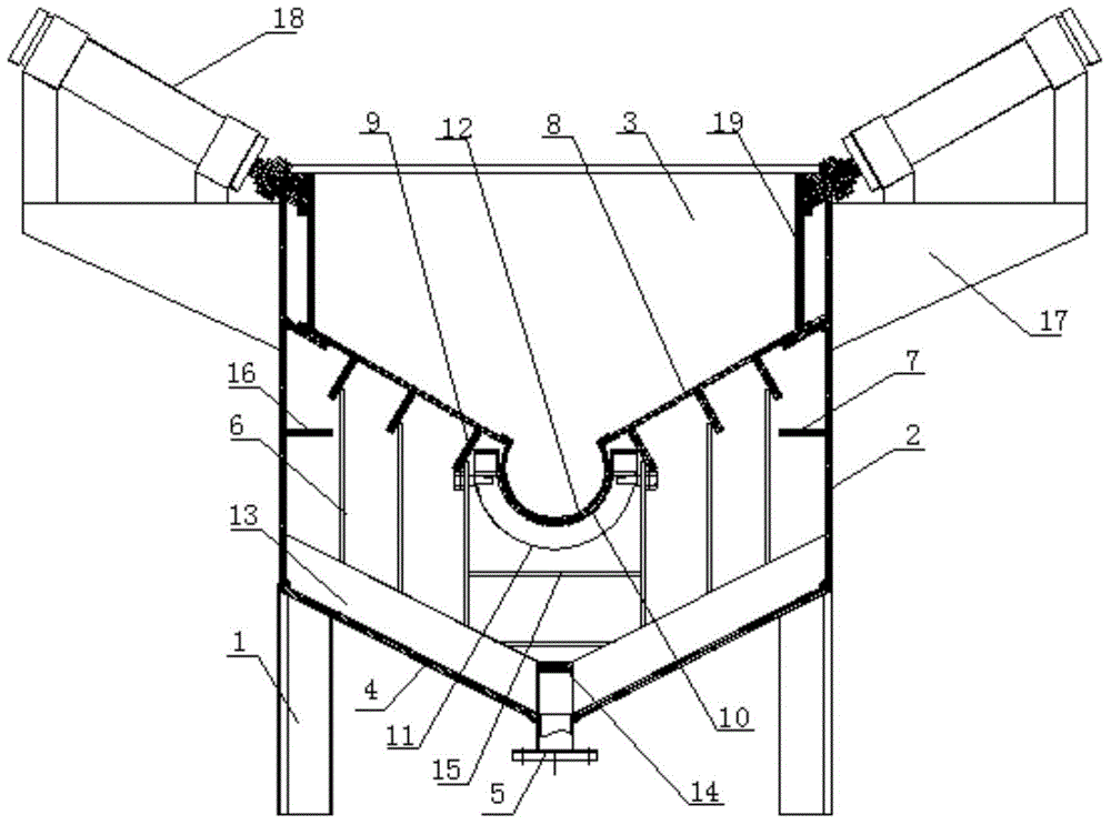
[0020] Such as Figure 1-Figure 3 As shown, a filter pushing mechanism for a product suction filter tank includes a bracket 1, and the bracket 1 supports a tank body surrounded by two side panels 2, two end panels 3 and a "V"-shaped bottom plate 4. The bottom of the tank body is provided with two first outlets 5, and a plurality of vertical end ribs 6 are symmetrically arranged on both sides of the inner wall of the end panel 3, and the lower end of the end ribs 6 Fixedly connected with the bottom plate 4, a filter screen support plate 7 is fixed on the side panel 2, a filter screen plate 8 is supported on the filter screen support plate 7, and the filter screen plate 8 is also supported by a bracket 9 On the end face vertical rib plate 6, an arc-shaped screen installation groove 10 is arranged betw...


PUM


Abstract

The invention discloses a filtering and pushing mechanism of an extraction and filtration groove for a product. The filtering and pushing mechanism comprises a bracket and a groove body, wherein two discharging openings are formed in the bottom of the groove body; a plurality of end-surface vertical-rib plates are arranged at the two sides of an end surface plate; a filtering-sieve supporting plate is fixedly arranged on a side-surface plate; a filtering sieve plate is supported on the filtering-sieve supporting plate, and is also supported on the end-surface vertical-rib plates by a supporting frame; an arc-shaped sieve net installing groove is formed between the two end-surface vertical-rib plates close to the lower end of the bottom plate and is internally provided with an arc-shaped sieve plate; a plurality of inclined-surface rib plates are fixedly arranged on the bottom plate; the two opposite inclined-surface rib plates are fixedly connected by a connecting plate; and a cylinder pushing mechanism is also fixedly arranged on the outer wall of the side surface. The filtering and pushing mechanism disclosed by the invention has the obvious effects that enough support can be provided for the filtering sieve plate; the structure is relatively stable; convenience is brought for cleaning the bottom of the extraction and filtration groove; and the pushing is carried out by a cylinder, so that rapid filtering can be achieved.

Description

technical field [0001] The invention relates to the technical field of chemical filter equipment, in particular to a filter pushing mechanism for a product suction filter tank. Background technique [0002] Suction filters are common devices in chemical plants and chemical laboratories. According to the needs of the operator, it can choose different materials and filter membranes with different filter pore sizes to achieve the functions of removing impurities in the solvent, purifying and sterilizing bacteria. In chromatographic analysis, the solvent filtered by it can not only effectively extend the service life of the chromatographic column, but also can significantly improve the data accuracy of the analysis system due to its vacuum degassing effect. [0003] However, in the prior art, only the two ends of the filter screen are supported, which often cannot provide enough support for the filter screen, so that the service life of the filter screen is reduced; the paralle...

Claims


Application Information

Patent Timeline
Patent Type & Authority Applications(China)
IPC IPC(8): B01D29/03B01D29/52B01D29/96
Inventor 刘锦科
Owner CHONGQING JINSHAN GENERAL MACHINERY MFGCO
Why Eureka
Try Eureka