Bender

A pipe bender and elevator technology, applied in metal processing equipment, feeding devices, positioning devices, etc., can solve the problems of low work efficiency, poor work stability, poor compatibility of pipe fittings, etc., achieve low cost, improve stability, and structure simple effect

Inactive Publication Date: 2016-06-01
无锡晶瑜智能机械有限公司
View PDF5 Cites 1 Cited by
  • Summary
  • Abstract
  • Description
  • Claims
  • Application Information

AI Technical Summary

Problems solved by technology

[0003] In the prior art, in the process of using the traditional pipe bending machine, there are problems such as low working efficiency, poor working stability, easy damage to parts, etc., and poor compatibility for bending pipe fittings of different sizes

Method used


Image

  • Bender
  • Bender
  • Bender

Examples


Embodiment Construction

[0016] Below the present invention will be further described in conjunction with the embodiment in the accompanying drawing:

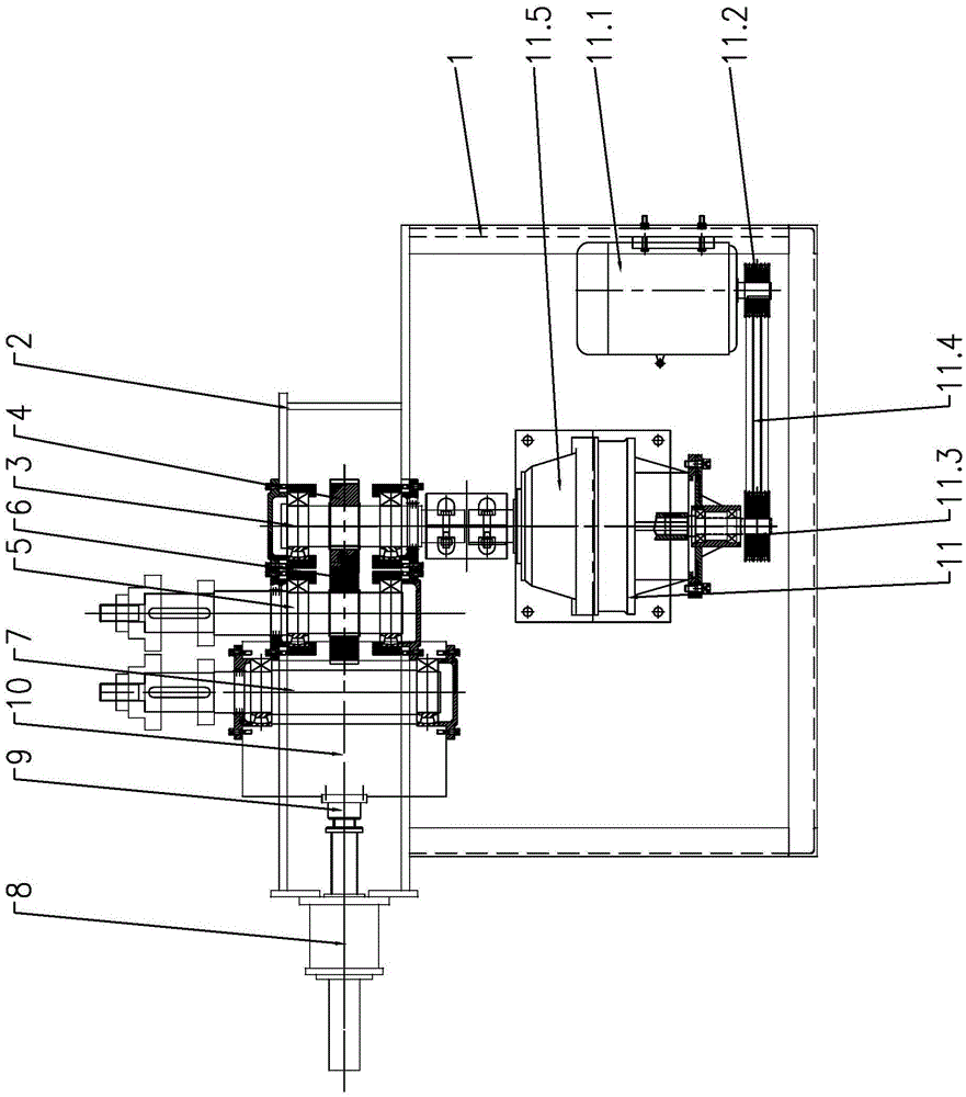
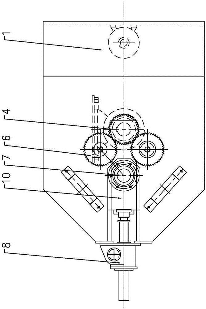
[0017] Such as Figure 1~2 As shown, the present invention mainly includes a main support 1, a drive shaft support 2, a drive shaft assembly 3, a drive gear 4, a fixed wheel assembly 5, a fixed wheel shaft gear 6, a moving wheel assembly 7, a worm screw lifter 8, a moving wheel support and a driving mechanism 11. The drive shaft support 2 and the drive mechanism 11 are fixed on the main support 1, the drive shaft support 2 is provided with a drive shaft assembly 3, and the left and right sides of the drive shaft assembly 3 are respectively provided with a fixed wheel assembly 5.

[0018] The drive shaft assembly 3 is provided with a drive gear 4, and the fixed wheel assembly 5 is provided with a fixed wheel shaft gear 6, and the drive gear 4 of the drive shaft assembly 3 meshes with the fixed wheel shaft gears 6 on the fixed wheel assemblies 5 on both ...


PUM


Abstract

The invention relates to a pipe bending machine, specifically relates to a rolling type pipe bending machine, and belongs to the technical field of pipe bending machines. The pipe bending machine comprises a main bracket, a driving shaft bracket, a driving shaft assembly, a driving gear, fixed wheel assemblies, fixed wheel shaft gears, a movable wheel assembly, a worm gear screw lifting machine, a movable wheel bracket and a driving mechanism; the driving shaft bracket and the driving mechanism are fixed on the main bracket; the driving shaft assembly is arranged on the driving shaft bracket; the fixed wheel assemblies are respectively arranged at the left side and the right side of the driving shaft assembly; the driving gear is arranged on the driving shaft assembly; the fixed wheel shaft gears are arranged on the fixed wheel assemblies; the driving gear of the driving shaft assembly are respectively connected with the fixed wheel shaft gears on the fixed wheel assemblies at two sides by an engaging manner. According to the pipe bending machine, a workpiece can be clamped through an upper pressing plate and a lower supporting plate during working, so that the pipe bending machine can stably work for bending, the working efficiency is increased, and the cost is relatively low; the distance from the upper pressing plate to the lower supporting plate can be adjusted to meet the requirement on bending the workpiece of different size, and therefore, the applicable scope is expanded.

Description

technical field [0001] The invention relates to a pipe bending machine, in particular to a rolling pipe bending machine, which belongs to the technical field of pipe bending machines. Background technique [0002] Pipe bending machines can be roughly divided into CNC pipe bending machines, hydraulic pipe bending machines and so on. The pipe bender mainly uses hydraulic pressure to perform winding bending of the pipe body with one or two bending radii in a cold state. It is widely used in the bending of various pipe fittings and wires in industries such as automobiles and air conditioners. [0003] In the prior art, the traditional pipe bending machine has problems such as low working efficiency, poor working stability, easy damage to parts, etc. during use, and poor compatibility for bending pipe fittings of different sizes. Contents of the invention [0004] The object of the present invention is to overcome the above disadvantages, thereby providing a pipe bender capabl...

Claims


Application Information

Patent Timeline
Patent Type & Authority Patents(China)
IPC IPC(8): B21D7/08B21D7/16B21D43/00
CPCB21D7/08B21D7/16B21D43/006
Inventor 赵军
Owner 无锡晶瑜智能机械有限公司
Why Eureka
Try Eureka