Engine valve lock clamp disassembling tool and method

A technology of engine valves and valve lock clips, which is applied in the field of tooling fixtures, can solve problems such as unreasonable operation steps, unreasonable disassembly and installation of valve lock clips, and difficult to detect scratches, so as to avoid scratches and make disassembly and installation simple Reliable, long-life effect

Active Publication Date: 2015-04-22
LUOYANG NORTHERN ENTERPRISES GROUP
View PDF10 Cites 14 Cited by
  • Summary
  • Abstract
  • Description
  • Claims
  • Application Information

AI Technical Summary

Problems solved by technology

Since the tools used are not special tools, the operation steps are not very reasonable, so the surface of the valve stem and the valve lock clip may be scratched during the process of disassembling and installing the valve lock clip, but these scratches are not easy to detect, and There will be no faults in the short period of time the engine is working. Only after a long time of work can the faults be displayed. At this time, it is irreparable.
Therefore, the maintenance personnel's method of removing and installing the valve lock clip is unreasonable.

Method used


Image

  • Engine valve lock clamp disassembling tool and method
  • Engine valve lock clamp disassembling tool and method
  • Engine valve lock clamp disassembling tool and method

Examples


Embodiment Construction

[0019] The present invention is described in conjunction with accompanying drawing and specific embodiment:

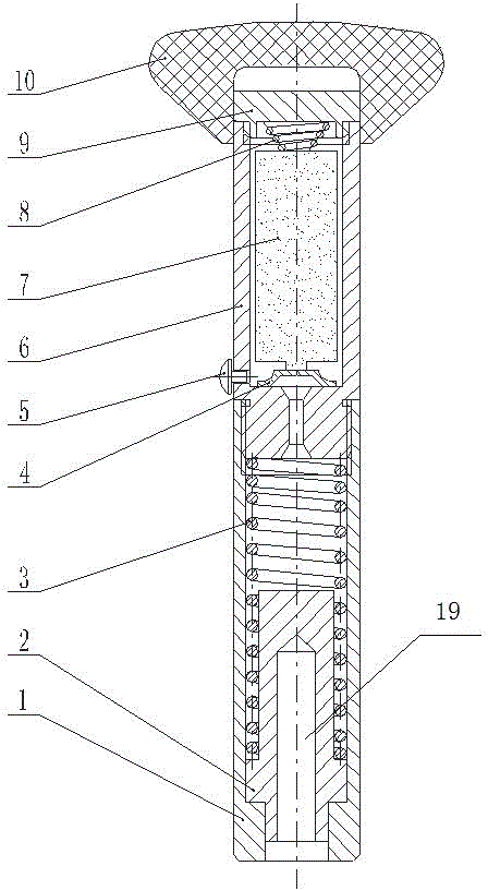
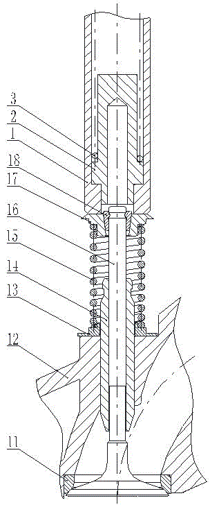
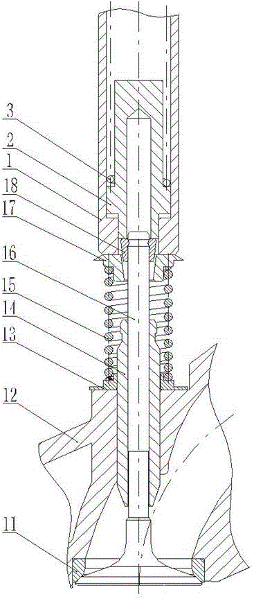
[0020] like figure 1Shown, a kind of engine valve lock clip dismounting tool, described dismounting tool includes valve spring seat pressure head 1, valve lock clamp pressure head 2 and handle 10; Described valve spring seat ring pressure head 1 center A cylinder with a stepped through hole, and the stepped through hole in the center of the valve spring seat ring pressure head 1 is a structure with a large top and a small bottom; the valve lock clamp pressure head 2 is located at the valve spring seat ring pressure head 1 In the center through hole of the valve spring seat ring pressure head 1, and can slide up and down in the center through hole of the valve spring seat ring pressure head 1; the upper end of the valve lock pressure head 2 is sleeved with a lock clamp pressure to reset the valve lock pressure head Head spring 3; the air door lock clamping head 2 is an...


PUM


Abstract

The invention belongs to the field of tool clamps, and provides an engine valve lock clamp disassembling tool and method. The engine valve lock clamp disassembling tool comprises a valve-spring retainer pressing head (1), a valve lock clamp pressing head (2) and a handle (10). The valve-spring retainer pressing head (1) is a barrel body with a stepped through hole formed in the center. The valve lock clamp pressing head (2) is located in the center through hole in the valve-spring retainer pressing head (1), the upper end of the valve lock clamp pressing head (2) is sleeved with a lock clamp pressing head spring (3), the valve lock clamp pressing head (2) is of an electromagnet structure, the handle (10) is arranged at the upper end of the valve-spring retainer pressing head (1), and a power source used for controlling the electromagnet to be powered on and off is arranged and corresponds to the valve lock clamp pressing head (2). The problem that the surfaces of a valve rod and a valve lock clamp are scratched in the disassembling and assembling process of the valve lock clamp is avoided, and the service life of the valve lock clamp and the service life of an engine are prolonged.

Description

technical field [0001] The invention belongs to the field of tooling fixtures, and in particular relates to a disassembly tool and a disassembly method for an engine valve lock clip. Background technique [0002] The valve of the engine is the passage for the gas in and out of the combustion chamber. The opening and closing of the valve is realized by reciprocating movement during work, and it must bear a great deal of alternating and impact load during the movement; in the prior art, the closing of the valve is completed by the valve spring Yes, the spring transmits the pretightening force to close the valve through the valve spring seat, and the valve lock clip is the part that limits the valve spring seat to ensure the pretightening force of the valve spring for closing the valve; The valve lock clip has a two-half structure, and the outer surface of the valve lock clip is a conical surface that matches the inner wall of the valve spring seat, and the inner surface is a s...

Claims


Application Information

Patent Timeline
Patent Type & Authority Applications(China)
IPC IPC(8): B25B27/00
CPCB25B27/14
Inventor 刘晨明艾东斌张祥李保明刘枫香崔湘豫
Owner LUOYANG NORTHERN ENTERPRISES GROUP
Why Eureka
Try Eureka