Pump station structure and pump station water in-out method

A pumping station and water inlet technology, which is applied in pumping stations, water supply devices, buildings, etc., can solve the problems of large area of ​​​​the pumping station, unstable flow pattern, and large inertia of water flow, so as to improve the land utilization rate and improve the efficiency of the pumping station. Small footprint effect

Active Publication Date: 2015-04-22
SHANGHAI URBAN CONSTR DESIGN RES INST GRP CO LTD
View PDF5 Cites 5 Cited by
  • Summary
  • Abstract
  • Description
  • Claims
  • Application Information

AI Technical Summary

Problems solved by technology

First, if all the underground structures of the pumping station are tiled, plus the layout of pumping station roads, greening, management rooms, power distribution rooms, etc., the entire pumping station will occupy a very large area
Second, if the angle between the center line of the pump station inlet tank culvert and the center line of the pump station outlet tank culvert is too small, it is easy to cause the water flow to flow in the inlet gradual expansion pipe, the sump of the pump room or the outlet water gradual expansion pipe with a large inertia. A strong flow along the outer wall is formed in a

Method used


Image

  • Pump station structure and pump station water in-out method
  • Pump station structure and pump station water in-out method
  • Pump station structure and pump station water in-out method

Examples


Embodiment 1

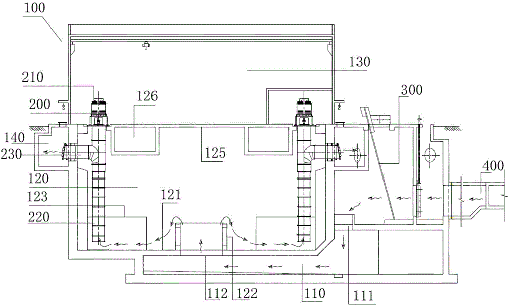
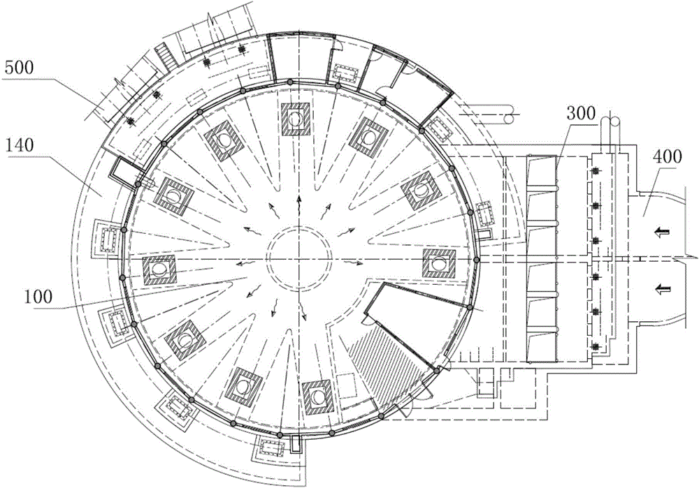
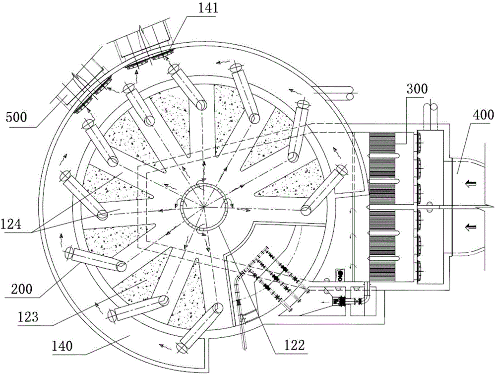
[0028] Such as figure 1 As shown, a pump station structure in this embodiment includes a pump room main body 100 and a water pump unit 200. The pump room main body 100 is sequentially arranged as a water inlet bottom layer 110, a water collection middle layer 120 and an electromechanical control top layer 130 from bottom to top. The water bottom layer 110 is provided with a water inlet 111 for introducing external water flow and a water distribution port 112 for introducing the water flow into the water collection intermediate layer, and the water distribution port 112 is conductively arranged on the bottom plate 121 of the water collection intermediate layer 120; The motor head 210 of the water pump unit 200 is arranged in the electromechanical control top layer 130, the water inlet pipe 220 of the water pump unit 200 is arranged in the water collection middle layer 120, and there is provided on the outside of the water collection middle layer 120 for leading out the water flo...

Embodiment 2

[0034] This embodiment proposes a method for pumping water in and out, including the following steps:

[0035]Step 1. The water flow directly falls into the water inlet bottom of the main body of the pump house.

[0036] Step 2: The water flows upwards and enters the water-collecting middle layer of the main body of the pump house.

[0037] Step 3: The water flow in the water-collecting intermediate layer is lifted by the water pump unit and then discharged into the water outlet pressure well.

[0038] Step 4, discharging the water from the outlet pressure well.

[0039] Specifically, such as Figure 1 to Figure 4 As shown, the water inlet and outlet method of the pumping station in this embodiment can be implemented on the pumping station structure described in the first embodiment, and the structure of the pumping station can directly refer to the description in the first embodiment, and will not be repeated here. The specific process is as follows:

[0040] Step 1: The ...


PUM


Abstract

The invention discloses a pump station structure and a pump station water in-out method. The pump station structure comprises a pump room body and water pump units, the pump room body is sequentially provided with a water inlet bottom layer, a water collecting middle layer and an electromechanical control top layer from bottom to top, a water inlet and a water distribution opening are formed in the water inlet bottom layer, and the water distribution opening is formed in a base plate of the water collecting middle layer in a through mode; water inlet pipes of the water pump units are arranged in the water collecting middle layer, water outlet pressure wells are arranged on the outer side of the periphery of the water collecting middle layer, and water flow is lifted by the water pump units to be guided into the water outlet pressure wells to be output outwards after entering the water collecting middle layer from the water inlet bottom layer. The pump room body of the pump station structure is divided into three layers, bottom center water distribution is achieved through the water inlet bottom layer and the water distribution opening, the upper portion peripheral water outlet is achieved in the mode that the water collecting middle layer is matched with the multiple water pump units and the water outlet pressure wells, and the problems of being large in floor space, limited in land utilization, small in pup station water inlet and water outlet pipe angle and the like are solved.

Description

technical field [0001] The invention relates to the technical field of pump station rectification, in particular to a pump station structure and a pump station water inlet and outlet method. Background technique [0002] The main structures of the pumping station from water inlet to water outlet include: water inlet box culvert, grid well, water inlet gradual expansion pipe, pump house sump well, water outlet high gate well and water outlet gradual expansion pipe. The most ideal water inlet method of the pumping station is : On the plane, the water inlet pipe and the water outlet pipe go straight in and out, and finally discharge into the river or downstream pipes; vertically, the elevation of each structure is gradually reduced, and the deepest part is raised at one time. In actual engineering, the narrow land is not enough to arrange the general plane of the pumping station according to the conventional design. First, if all the underground structures of the pumping stati...

Claims


Application Information

Patent Timeline
IPC IPC(8): E03B5/00
CPCE03B5/02
Inventor 季洪金唐群徐莹
Owner SHANGHAI URBAN CONSTR DESIGN RES INST GRP CO LTD
Why Eureka
Try Eureka