Machine tool main shaft speed changing box

A technology of machine tool spindle and gearbox, applied in mechanical equipment, gear transmission, components with teeth, etc., can solve the problem of large error between meshing position and static state, shortened life of support bearing, and increased transmission gap due to gear wear on the shaft. and other problems to achieve the effect of reducing processing difficulty, increasing reliability and enhancing rigidity

Inactive Publication Date: 2015-04-22
SHANDONG YONGHUA MACHINERY
View PDF7 Cites 2 Cited by
  • Summary
  • Abstract
  • Description
  • Claims
  • Application Information

AI Technical Summary

Problems solved by technology

[0002] At present, the multi-gear spindle gearboxes of machine tools all adopt gear transmission. When shifting gears, an air cylinder or hydraulic cylinder is used to control the shift fork. The shifting gear slides on the spline shaft to complete the shift action. Generally, more than two spline shafts need to be installed. It needs space for the gear to slide on the spline shaft, which becomes a long shaft (long and unsupported in the middle) in the transmission chain. When the power is transmitted, the flower shaft is easy to deform, the gear gap becomes larger, and the meshing position The large error with the static state will easily cause the life of the supporting bearings at both ends of the shaft to decrease, the wear of the gears on the shaft will increase, and the transmission gap will change with the increase of torque. Obvious disadvantages

Method used


Image

  • Machine tool main shaft speed changing box

Examples


Embodiment Construction

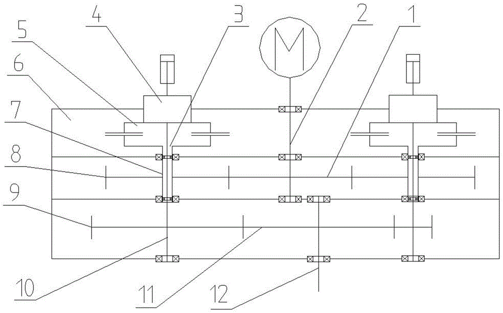
[0010] The specific embodiment of the present invention will be described in further detail below by describing the two-speed gearbox with reference to the accompanying drawings.

[0011] Such as figure 1 The shown machine tool spindle gearbox includes a box body 6, an input shaft 2 and an output shaft 12, the input shaft 2 is fixedly connected with the main input gear 1, the output shaft 2 is fixedly connected with the main output gear 11, the input shaft 2 and the output shaft The shafts 12 are parallel and are connected to the box body 6 through bearings. At least one set of transmission modules 3 are arranged in the box body 6. The transmission module 3 includes a clutch 4, a hollow shaft 7 and a solid shaft 10. The upper part of the hollow shaft 7 is connected to the lower half of the clutch 4. fixed, the lower part of the hollow shaft 7 is fixed with a hollow shaft gear 8 meshing with the main input gear 1, the upper part of the solid shaft 10 is fixedly connected with t...


PUM


Abstract

The invention relates to a machine tool main shaft speed changing box which comprises a box body, an input shaft and an output shaft. The input shaft is fixedly connected with a main input gear. The output shaft is fixedly connected with a main output gear. A speed changing group comprises a clutch, a hollow shaft and a solid shaft. The upper portion of the hollow shaft and the lower half side of the clutch are fixed. The lower portion of the hollow shaft is fixedly provided with a hollow shaft gear meshed with the main input gear. The upper portion of the solid shaft is fixedly connected with the upper half side of the clutch. The lower portion of the solid shaft is provided with a solid shaft gear meshed with the main input gear. The solid shaft is connected into the hollow shaft in a sleeved mode through a bearing, and the solid shaft and the hollow shaft are coaxial. Transmission chain rigidity is improved, the service life of the gears and a supporting bearing on a shaft is prolonged, the cavity size in the speed changing box is reduced, so that a gear box is stable, the design of an inner-outer sliding spline in the transmission main shaft speed changing box is avoided, the machining difficulty of the shaft gears is lowered, and reliability is improved.

Description

technical field [0001] The invention belongs to the field of machine tool transmission equipment, and in particular relates to a machine tool spindle gearbox. Background technique [0002] At present, the multi-gear spindle gearboxes of machine tools all adopt gear transmission. When shifting gears, an air cylinder or hydraulic cylinder is used to control the shift fork. The shifting gear slides on the spline shaft to complete the shift action. Generally, more than two spline shafts need to be installed. It needs space for the gear to slide on the spline shaft, which becomes a long shaft (long and unsupported in the middle) in the transmission chain. When the power is transmitted, the flower shaft is easy to deform, the gear gap becomes larger, and the meshing position The large error with the static state will easily cause the life of the support bearings at both ends of the shaft to decrease, the wear of the gears on the shaft to increase, and the transmission gap to chang...

Claims


Application Information

Patent Timeline
Patent Type & Authority Applications(China)
IPC IPC(8): F16H3/10F16H61/26
CPCF16H3/10F16H61/26
Inventor 孔渊哲陈舟孔昌张宝雷葛振刚
Owner SHANDONG YONGHUA MACHINERY
Why Eureka
Try Eureka