
Electronically controlled differential lock control mechanism and control method

A control mechanism and differential lock technology, applied in the control device, differential transmission device, transmission device control and other directions, can solve the problems of high dependence on air source and air pressure, unable to realize the requirement of shifting gear, unable to shift gear, etc. Easy to shift gear, no need to adjust and maintain, easy to shift gear

Active Publication Date: 2017-04-12
DONGFENG MOTOR CORP HUBEI
View PDF8 Cites 0 Cited by
  • Summary
  • Abstract
  • Description
  • Claims
  • Application Information

AI Technical Summary

Problems solved by technology

This structure is highly dependent on the air source and air pressure, and often encounters risks such as air leakage, card issuance, and failure to shift gears, especially when the car is parked or turned off.

Method used


Image

  • Electronically controlled differential lock control mechanism and control method
  • Electronically controlled differential lock control mechanism and control method
  • Electronically controlled differential lock control mechanism and control method

Examples


Embodiment Construction

[0026] The present invention will be further described in detail below in conjunction with the accompanying drawings and specific embodiments to facilitate a clear understanding of the present invention, but they do not limit the present invention.

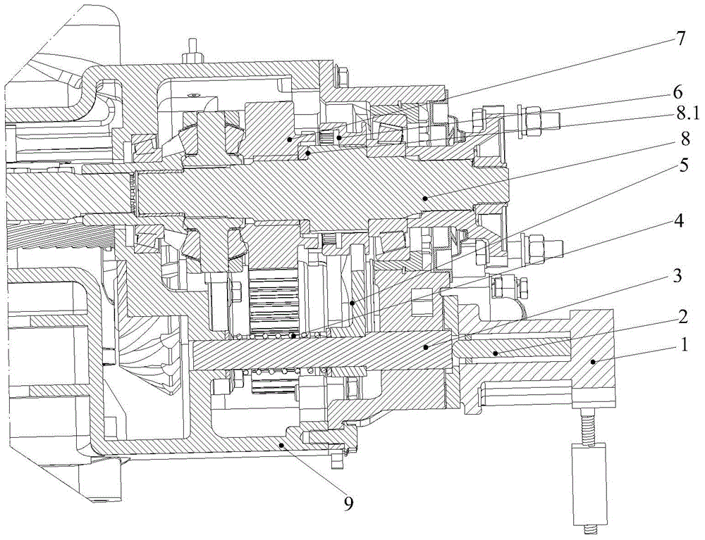
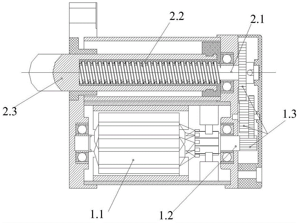
[0027] like figure 1 As shown, an electronically controlled differential lock control mechanism of the present invention includes a reducer housing 9, the reducer housing 9 is provided with a shift fork shaft 3, and a shift fork is sleeved on the shift fork shaft 3 5 and the return spring 4, the shift fork 5 is limitedly connected with the engagement sleeve 6, the engagement sleeve 6 is set on the main shaft 8, and the axial limit sleeve on the main shaft 8 is provided with the engagement sleeve 6 The drive gear 7, the reducer housing 9 is also provided with an electric control mechanism 1, the output end of the electric control mechanism 1 is connected to a push rod mechanism 2 that can move linearly, and the push rod mechanism 2...


PUM


Abstract

The invention relates to an electrically-control type differential lock control mechanism, and belongs to the technical field of electrically-control type automobile drive axles. The electrically-control type differential lock control mechanism comprises a reducer shell. A shifting fork shaft is arranged in the reducer shell and sleeved with a shifting fork and a return spring. The shifting fork is connected with a shift sleeve in a limiting mode. The shift sleeve is arranged on a main shaft in a sleeving mode. An axial limiting sleeve on the main shaft is provided with a drive gear capable of being meshed with the shift sleeve. An electric control mechanism is further arranged in the reducer shell. The output end of the electric control mechanism is connected with a push rod mechanism capable of linearly moving. The push rod mechanism and the shifting fork shaft are coaxially arranged. The push rod mechanism makes axial contact with the shifting fork shaft in a connected mode. The invention further discloses an electrically-control differential lock control method. By means of the electronically-control differential lock control mechanism and method, locking and separation of a differential lock can be achieved under the conditions that no gas source exists when an automobile is motionless and after parking and flameout are conducted, gear shifting is convenient to conduct, and the locking requirement required in the hill-holding brake process is met.

Description

technical field [0001] The invention relates to an electronically controlled vehicle drive axle, in particular to an electronically controlled differential lock control mechanism and a control method. Background technique [0002] In the all-wheel drive or double-axle drive system, the main reducer and the transfer box of the middle and rear axles need to be equipped with an inter-axle differential or an inter-wheel differential to ensure that the wheels of the car are not equal when turning. It can rotate at corresponding different speeds, so as to meet the requirements of vehicle driving kinematics. However, for off-road vehicles, there must be a differential lock function if there is a differential, otherwise the wheels on one side will slip, which will seriously affect the passability of the vehicle. At present, the differential locking function of the differential of the existing drive axle or transfer case assembly is basically pneumatically controlled, and the operat...

Claims


Application Information

Patent Timeline
Patent Type & Authority Patents(China)
IPC IPC(8): F16H63/30B60K23/04
CPCF16H48/28F16H48/34
Inventor 谢锡春阮仁新汪振晓周寅鹏付邦璀张皓
Owner DONGFENG MOTOR CORP HUBEI
Learn More