LED fluorescent lamp

A technology of LED fluorescent lamps and LED lamps, applied in the field of fluorescent lamps, can solve the problems of labor and time-consuming, LRD fluorescent lamps cannot be generalized, etc.

Inactive Publication Date: 2015-04-22
HENAN ZHONGYUNCHUANG OPTOELECTRONICS TECH
View PDF9 Cites 1 Cited by
  • Summary
  • Abstract
  • Description
  • Claims
  • Application Information

AI Technical Summary

Problems solved by technology

[0002] As the country vigorously promotes the implementation of energy-saving and emission-reduction strategies, LED fluorescent lamps are more and more widely used due to their energy-saving and environmental protection features, and there is a tendency to gradually replace traditional fluorescent lamps. However, the lamp holders of traditional fluorescent lamps are equipped with inductive or electronic ballasts. When installing LED fluorescent lamps, it is necessary to modify the circuit inside the lamp holder, which is labor-intensive and time-consuming. In addition, the fluorescent lamp lamp holders in my country use double-ended power supply, but the lamp holders of fluorescent lamps in many countries use single-end power supply. The existing LRD Fluorescent lamps cannot be universalized

Method used


Image

  • LED fluorescent lamp
  • LED fluorescent lamp
  • LED fluorescent lamp

Examples


Embodiment Construction

[0012] The technical solutions of the present invention will be described in further detail below through specific implementation methods.

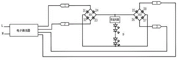
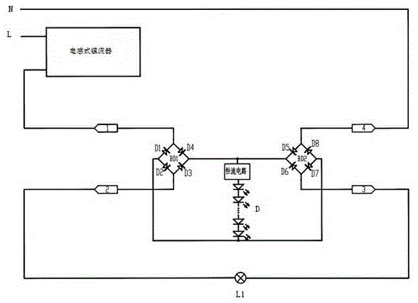
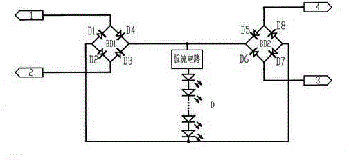
[0013] Examples such as figure 1 As shown, an LED fluorescent lamp includes a rectifier bridge stack composed of D1, D2, D3 and D4, a rectifier bridge stack composed of D5, D6, D7, D8 and LED lamp tubes, and the two rectifier bridge stacks The positive poles of the DC output terminals are all connected to the input terminals of the constant current circuit, the output terminals of the constant current circuit are connected to the positive poles of the light-emitting diode D, and the negative poles of the light-emitting diode D are connected to the negative poles of the DC output terminals of the two rectifier bridge stacks, so The light-emitting diode D is located in the LED lamp tube, the two AC input ends 1, 2 of one rectifier bridge stack are arranged at one end of the LED lamp tube, and the two AC input ends of the other rectifier bri...


PUM


Abstract

The invention provides an LED fluorescent lamp. The LED fluorescent lamp comprises two bridge rectifiers and an LED modulator tube, wherein the positive electrodes of the direct current output ends of the two bridge rectifiers are connected with the input end of a constant-current circuit; the output end of the constant-current circuit is connected with the positive electrode of a light emitting diode; the negative electrode of the light emitting diode is connected with the negative electrodes of the direct current output ends of the two bridge rectifiers; the light emitting diode is located in the LED modulator tube; two alternating current input ends of one of the bridge rectifier are arranged at one end of the LED modulator tube; two alternating current input ends of the other bridge rectifier are arranged at the other end of the LED modulator tube. Any two alternating current input ends are selected from the four alternating current input ends of the two ends of the LED modulator tubes to be connected, so that the LED fluorescent lamp can normally work. The LED fluorescent lamp can meet the connection requirements of domestic and overseas lamp holders at the same time, achieve generalized installation, reduce installation difficulty, decrease the speed of elimination of old lamp holders, achieve reutilization of resources and save existing resources.

Description

technical field [0001] The invention relates to a fluorescent lamp, in particular to an LED fluorescent lamp. Background technique [0002] As the country vigorously promotes the implementation of energy-saving and emission-reduction strategies, LED fluorescent lamps are more and more widely used due to their energy-saving and environmental protection features, and there is a tendency to gradually replace traditional fluorescent lamps. However, the lamp holders of traditional fluorescent lamps are equipped with inductive or electronic ballasts. When installing LED fluorescent lamps, it is necessary to modify the circuit inside the lamp holder, which is labor-intensive and time-consuming. In addition, the fluorescent lamp lamp holders in my country use double-ended power supply, but the lamp holders of fluorescent lamps in many countries use single-end power supply. The existing LRD Fluorescent lamps cannot be universalized. [0003] How to make LED fluorescent lamps not only ...

Claims


Application Information

Patent Timeline
Patent Type & Authority Applications(China)
IPC IPC(8): F21S2/00H05B37/02F21Y101/02
CPCF21S2/00F21Y2101/00H05B47/10
Inventor 王同波
Owner HENAN ZHONGYUNCHUANG OPTOELECTRONICS TECH
Why Eureka
Try Eureka