Logistics packing case fixing and locking device

A lock device and container technology, applied in the field of warehousing and logistics, can solve problems such as failure to meet the requirements for rapid access and use of logistics containers, safety accidents, and inability to lock the logistics containers, so as to meet the requirements of access and use and save money. Input cost, locking effect

Active Publication Date: 2017-02-15
镇江兴港国际物流有限公司
View PDF12 Cites 1 Cited by
  • Summary
  • Abstract
  • Description
  • Claims
  • Application Information

AI Technical Summary

Problems solved by technology

[0002] At present, with the development of the domestic economy, the logistics industry has also developed by leaps and bounds. In the field of warehousing and logistics, due to the increasing variety of materials and the higher and higher requirements for the access speed of materials, the storage of materials Logistics puts forward higher requirements. Different materials are generally placed in different logistics containers. In the warehouse for storing logistics containers, the most used ones are shelves for storing logistics containers. However, in the current technology , the vast majority of logistics containers are simply stacked and placed on the shelf. This placement will allow the logistics container to move back and forth, left and right on the shelf under the action of external force, and in the state of stacking the logistics container, it is necessary to It can only be taken out by moving away from each other. Therefore, the logistics container cannot be better locked on the shelf, and it is easy to cause safety accidents. Such a placement method cannot meet the existing requirements for rapid access to the logistics container.

Method used


Image

  • Logistics packing case fixing and locking device
  • Logistics packing case fixing and locking device
  • Logistics packing case fixing and locking device

Examples


Embodiment Construction

[0017] The preferred embodiments of the present invention will be described in detail below in conjunction with the accompanying drawings, so that the advantages and features of the present invention can be more easily understood by those skilled in the art, so as to define the protection scope of the present invention more clearly.

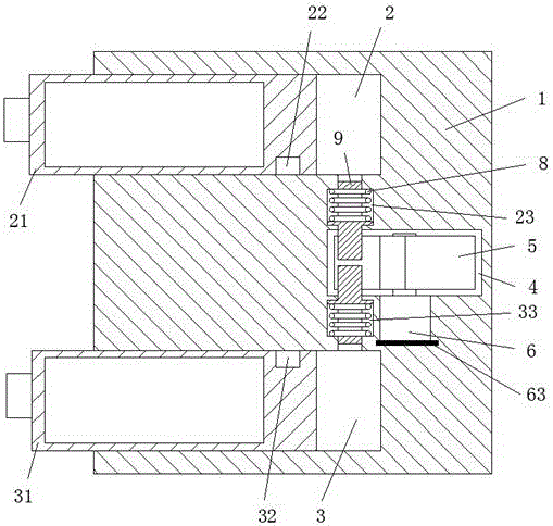
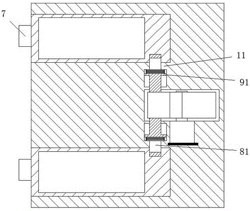
[0018] refer to Figure 1-5 As shown, a logistics container locking device of the present invention includes a frame body 1, a rear box cavity 2 and a front box cavity 3 arranged in the frame body 1, and the rear box cavity can be slidably arranged in the left and right directions respectively. 2 and the rear box body 21 and the front box body 31 in the front box cavity 3, and the rear lock hole 22 arranged on the right side front of the rear box body 21, and the front lock hole 32 arranged on the right side rear side of the front box body 31, A rear sliding chamber 23 and a front sliding chamber 33 are also provided in the frame body 1, and a dr...


PUM


Abstract

The invention discloses a logistics packing case fixing and locking device. The logistics packing case fixing and locking device comprises a frame body (1), a rear case cavity (2), a front case cavity (3), a rear case body (21), a front case body (31), a rear lock hole (22) and a front lock hole (32); the rear case cavity (2) and the front case cavity (3) are arranged in the frame body (1), the rear case body (21) is arranged in the rear case cavity (2) in a left-and-right direction sliding manner, the front case body (31) is arranged in the front case cavity (3) in a left-and-right direction sliding manner, the rear lock hole (22) is formed in the front of the right side of the rear case body (21), and the front lock hole (32) is formed in the rear of the right side of the front case body (31); a rear sliding cavity (23) and a front sliding cavity (33) are further formed in the frame body (1), a drive rotation containing bin (4) is communicated and connected between the rear sliding cavity (23) and the front sliding cavity (33), the rear sliding cavity (23) is communicated and connected with the right side of the rear case cavity (2), the front sliding cavity (33) is communicated and connected with the right side of the front case cavity (3), and the rear sliding cavity (23) and the front sliding cavity (33) are internally and symmetrically provided with fixing and locking devices which can slide in a front-and-back manner.

Description

technical field [0001] The invention relates to the field of warehousing and logistics, in particular to a logistics container locking device. Background technique [0002] At present, with the development of the domestic economy, the logistics industry has also developed by leaps and bounds. In the field of warehousing and logistics, due to the increasing variety of materials and the higher and higher requirements for the access speed of materials, the storage of materials Logistics puts forward higher requirements. Different materials are generally placed in different logistics boxes. In the warehouse for storing logistics boxes, the most used ones are shelves for storing logistics boxes. However, in the current technology , the vast majority of logistics containers are simply stacked and placed on the shelf. This placement will allow the logistics container to move back and forth, left and right on the shelf under the action of external force, and in the state of stacking...

Claims


Application Information

Patent Timeline
Patent Type & Authority Applications(China)
IPC IPC(8): B65G1/02
CPCB65G1/02
Inventor 王远
Owner 镇江兴港国际物流有限公司
Why Eureka
Try Eureka