
An automatic monitoring device for central air-conditioning energy saving and emission reduction

A central air-conditioning, energy-saving and emission-reducing technology, which is applied to control input related to air characteristics, space heating and ventilation control input, space heating and ventilation, etc. Data consumption interface and other issues

Active Publication Date: 2017-06-30
泰安市智慧能源科技有限公司
View PDF1 Cites 0 Cited by
  • Summary
  • Abstract
  • Description
  • Claims
  • Application Information

AI Technical Summary

Problems solved by technology

For example, the Chinese invention patent whose publication number is CN101110097A discloses a kind of energy-saving control by controlling the power supply of air-conditioning equipment or central air-conditioning terminal equipment through the switch of the window. This invention is not suitable for the quantitative management of air-conditioning in current enterprises and institutions. There is no interface for collecting energy consumption data, and there is no centralized monitoring equipment
There is also an energy-saving control system based on the Internet of Things and wireless sensor network technology. Due to the small signal range of the wireless sensor network, the number of connections between the base station and the terminal is limited, generally less than 10, which limits its practicability

Method used


Image

  • An automatic monitoring device for central air-conditioning energy saving and emission reduction
  • An automatic monitoring device for central air-conditioning energy saving and emission reduction
  • An automatic monitoring device for central air-conditioning energy saving and emission reduction

Examples


Embodiment Construction

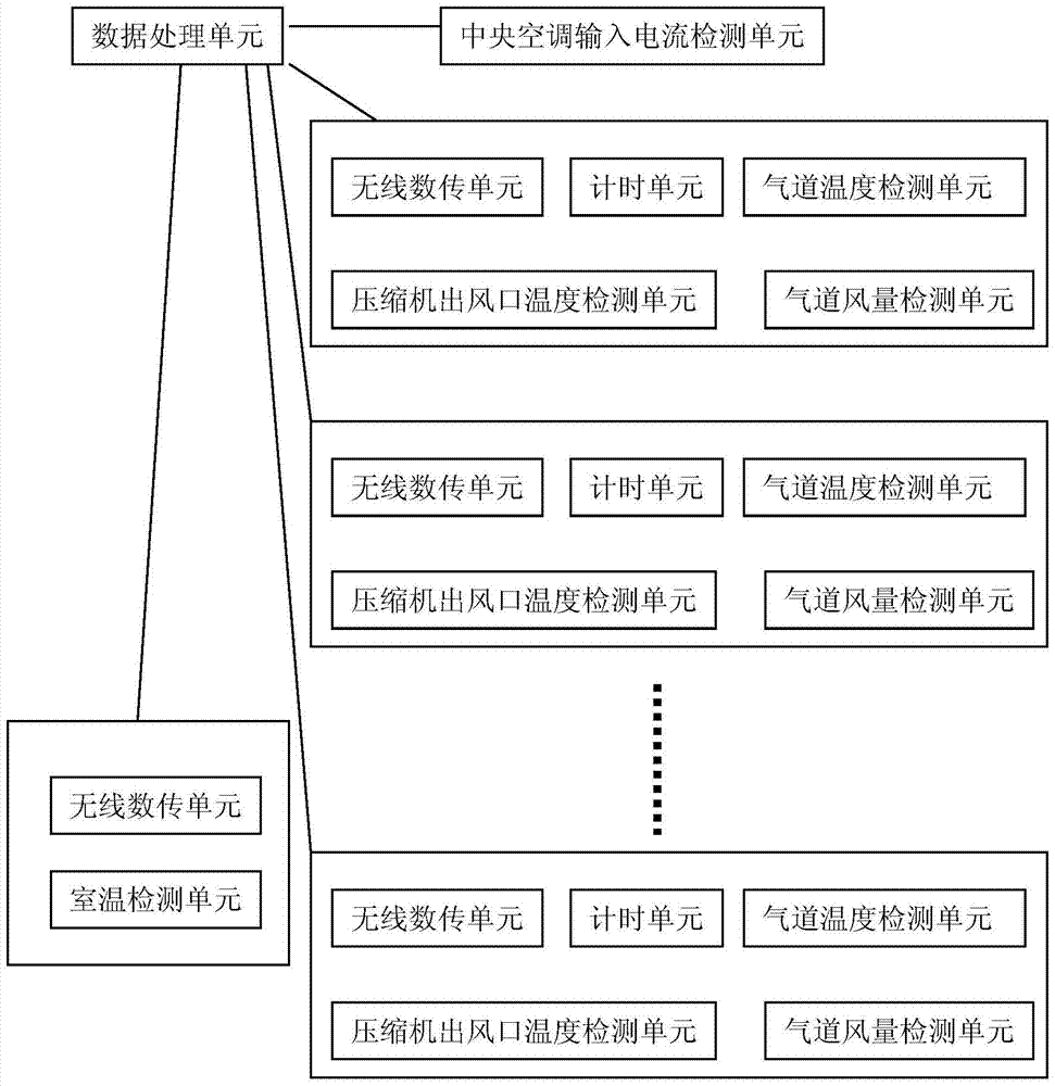
[0019] The following will be combined with figure 1 The present invention is further described.

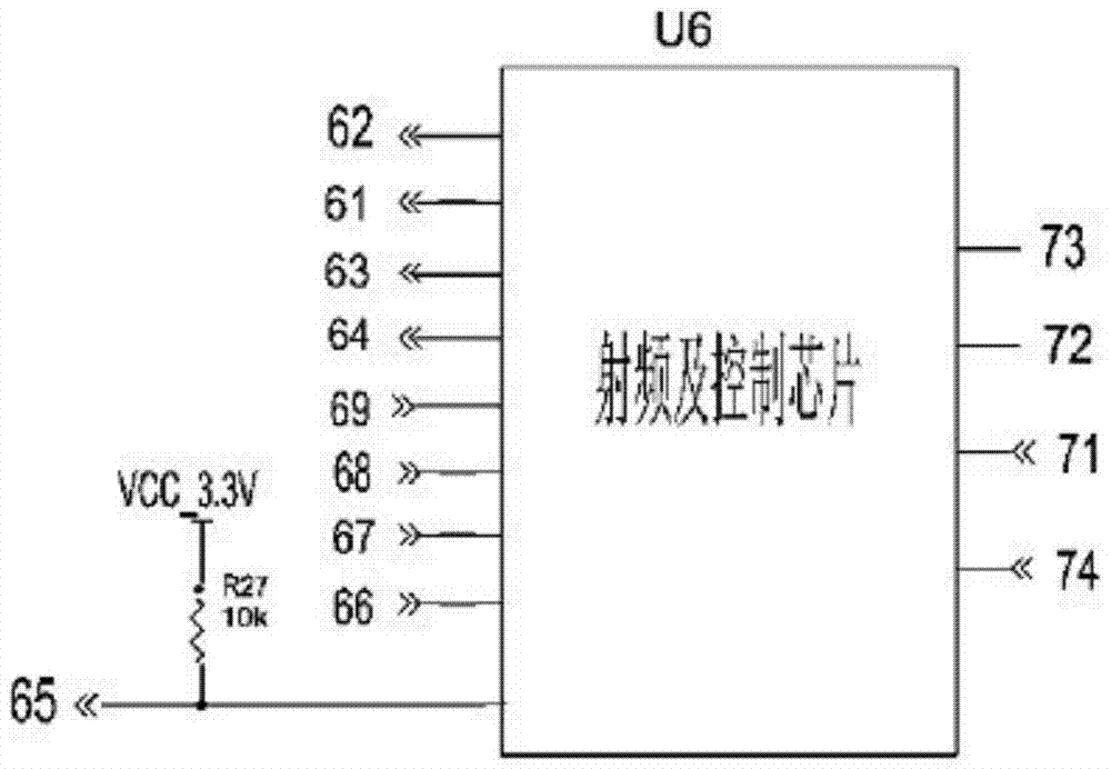
[0020] see figure 1 , central air-conditioning energy-saving emission reduction automatic monitoring device, including ARM7-based embedded processing unit, compressor air outlet temperature detection unit, air duct temperature detection unit, air duct air volume detection unit, and timing unit connected to the air duct temperature detection unit and a radio frequency unit, a central air conditioner input current detection unit and a room temperature detection unit, wherein the room temperature detection unit is arranged in each room and includes a radio frequency unit and an alarm unit, and the airway temperature detection unit is distributed in the central The air outlet of the air conditioner compressor is connected to the air passage of each room, and the air passage temperature detection unit, air passage air volume detection unit, timing unit and radio frequency unit are int...


PUM


Abstract

The invention provides an automatic monitoring device for energy conservation and emission reduction of a central air conditioner. The automatic monitoring device aims at solving the problem that energy conservation and emission reduction operation of the central air conditioner is lack of effective supervision, measurement and control. The automatic monitoring device comprises a data processing unit, compressor air outlet temperature detection units, air flue temperature detection units, air flue blast capacity detection units, timing units, wireless data transmission units, a central air conditioner input current detection unit and indoor temperature detection units, wherein the timing units and the wireless data transmission units are connected with the air flue temperature detection units, the indoor temperature detection units are arranged in rooms and comprise the wireless data transmission units and alarm units; the air flue temperature detection units are distributed in air flues from an air outlet of a compressor of the central air conditioner to the rooms; the air flue temperature detection units, the air flue blast capacity detection units, the timing units and the wireless data transmission units are integrated. The automatic monitoring device can effectively monitor whether the ratio of energy consumption of the central air conditioner to the generated refrigeration and heating effect is proper or not and can conveniently remind users to find the positions with abnormal energy consumption in time.

Description

technical field [0001] The invention relates to the technical field of distributed monitoring, and more specifically, to an automatic monitoring device for central air-conditioning energy saving and emission reduction. Background technique [0002] The preciousness and scarcity of energy have become a problem that society must face today, and our country also proposes to carry out energy conservation and emission reduction work. In many buildings, it is especially related to the maintenance and use of central air conditioning. [0003] On the one hand, many places have regulations on the setting temperature of air conditioners, for example, the temperature of indoor air conditioners in public buildings should not be lower than 26°C in summer. However, due to the large flow of people in public buildings, in order to maintain a good low temperature effect, the temperature setting in many places is lower than 26°C. However, there is no means to monitor the working status and t...

Claims


Application Information

Patent Timeline
Patent Type & Authority Patents(China)
IPC IPC(8): F24F11/02
CPCF24F11/30F24F11/58F24F11/62F24F11/89F24F2110/00F24F2110/10F24F2110/30
Inventor 康爱国
Owner 泰安市智慧能源科技有限公司
Learn More