Optical touch screen system with calibration function
An optical touch screen, functional technology, applied in the input/output process of data processing, instruments, electrical digital data processing, etc., to achieve the effect of easy installation and free choice
- Summary
- Abstract
- Description
- Claims
- Application Information
AI Technical Summary
Problems solved by technology
Method used
Image
Examples
specific Embodiment 1
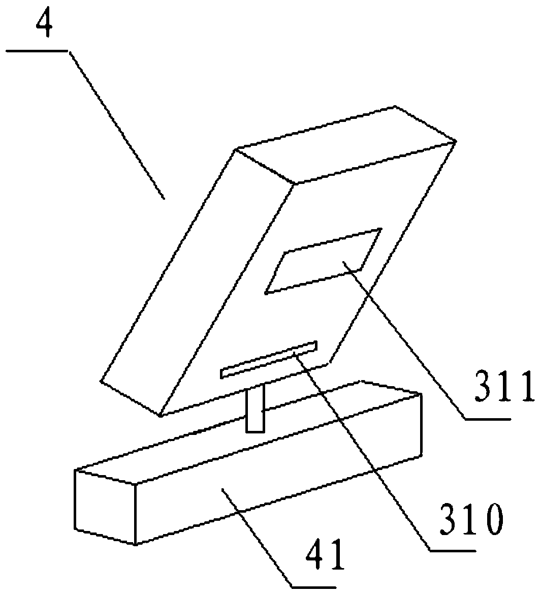
[0045] refer to image 3 The touch position detection module 3 may be a touch position detection module that adopts the structural principle of the click position detection module for determining the click position, which is adopted by the existing virtual laser keyboard. It includes an infrared emitting source 310 and an infrared signal receiving module 311 . An infrared image positioning device is arranged inside, and the infrared signal receiving module 311 is connected to the infrared image positioning device. In order to eliminate the signal blind area at a short distance, the optical signal receiving part of the infrared signal receiving module 311 is relatively protruding and inclined downward.
[0046] The click position detection module adopted in the existing virtual laser keyboard can better detect the click position and accurately locate it. It can be directly applied to the present invention to detect and locate the touch point. The click position of the virtua...
specific Embodiment 2
[0052] The touch position detection module 3 can also determine the touch point by adopting the technical solution described in the patent titled "Laser Remote Control Signal Receiver and Its Supporting Laser Remote Control Signal Transmitter" and the application number is 200810035508.x The position of the touch position detection module 3. This needs to be used in conjunction with a dedicated touch pen that can emit light beams. Take the light point presented by the light beam on the display screen 6 as the touch point.
[0053] refer to Figure 5 , Image 6 The touch position detection module 3 includes a photosensitive element group, and the photosensitive element group includes at least two photosensitive elements, and the photosensitive element group is covered with an optical signal directional receiving device 321 for filtering non-correlated direction optical signals. The photosensitive element 321 is connected to a signal processing module 322 for processing elect...
specific Embodiment 3
[0059] refer to Figure 8 , the touch position detection module 3 includes a camera 33 for capturing images on the display screen 6 . The camera device 33 is connected to the microprocessor module 1 and transmits the touch point image to the microprocessor module 1 . The microprocessor module 1 is a microprocessor module 1 capable of determining the position of the touch point through the image of the touch point. Existing image interaction technologies can already fulfill the above technical requirements well, so no more details are given here.
[0060] It can be applied to mobile phones, handheld computers, desktop computers, projector systems and other equipment. Especially for the projector system, it can realize the remote control of the host computer at the screen. In order to further reduce or even eliminate blind spots, the above design is particularly easy to install at the corner of the display screen 6 .
PUM
 Abstract
Description
Claims
Application Information
 - R&D
- Intellectual Property
- Life Sciences
- Materials
- Tech Scout
- Unparalleled Data Quality
- Higher Quality Content
- 60% Fewer Hallucinations
Browse by: Latest US Patents, China's latest patents, Technical Efficacy Thesaurus, Application Domain, Technology Topic, Popular Technical Reports.
© 2025 PatSnap. All rights reserved.Legal|Privacy policy|Modern Slavery Act Transparency Statement|Sitemap|About US| Contact US: help@patsnap.com


