A bearing ring demagnetization device

A bearing ring, demagnetization technology, applied in the field of bearing processing, can solve the problems of large remanence, equipment damage, affecting equipment performance, etc.

Inactive Publication Date: 2017-02-22
HENAN MECHANICAL & ELECTRICAL ENG COLLEGE
View PDF8 Cites 0 Cited by
  • Summary
  • Abstract
  • Description
  • Claims
  • Application Information

AI Technical Summary

Problems solved by technology

[0002]The surface of the bearing ring after grinding is often stuck with iron filings and other debris, which must be completely cleaned before use to prevent damage to the equipment
Due to the extensive use of magnetic chucks and other devices during the grinding process, the surface of the bearing ring is magnetized, which makes iron filings and other debris adhere firmly and is not easy to be cleaned. Therefore, it must be demagnetized and ensure its residual magnetic strength. It is less than a certain value (0.3mT stipulated in GB). With the development of industrial technology, the value stipulated by the national standard is sometimes difficult to meet the processing requirements, and the traditional solution produces a large remanence, especially for thinner ones. The residual magnetism at the edge of the ultra-thin ferrule is often too large, and in many cases even the basic requirements of the national standard are difficult to meet, resulting in difficulty in washing, and subsequent use on the equipment will seriously affect the performance of the equipment

Method used


Image

  • A bearing ring demagnetization device
  • A bearing ring demagnetization device
  • A bearing ring demagnetization device

Examples


Embodiment Construction

[0040] In order to make the object, technical solution and advantages of the present invention clearer, the present invention will be further described in detail below in conjunction with the accompanying drawings and embodiments. It should be understood that the specific embodiments described here are only used to explain the present invention, not to limit the present invention.

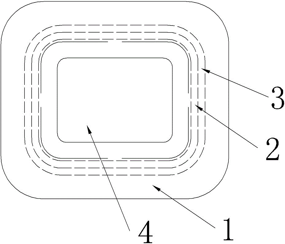
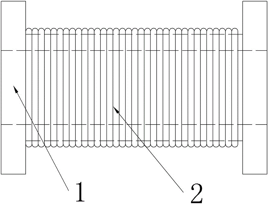
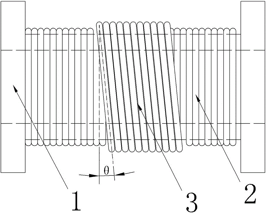
[0041] Please refer to Figure 1-17 , a bearing ring demagnetization device of the present invention, see for details Figure 4 , mainly including: CPU unit, first-layer coil 2, second-layer coil 3, used to detect the external bearing ring signal and transmit the bearing ring signal to the sensor of the CPU unit, used to input the demagnetization curve parameters to the CPU unit And the data input and display unit that displays the demagnetization parameter information is connected between the CPU unit and the first layer coil 2, and the first drive circuit that receives the demagnetization curve ...


PUM


Abstract

The invention relates to the field of bearing processing, in particular to a demagnetization device for a bearing ring. The sensor in the demagnetization device detects the external bearing ring signal and transmits it to the CPU unit. The demagnetization curve parameters are input to the CPU unit through the data input and display unit and the demagnetization parameter information is displayed. The first and second drive circuits receive the demagnetization curve parameters of the CPU unit respectively. Control the current change of the first and second layer coils, thereby controlling the change of the demagnetization magnetic field to achieve the demagnetization effect. The angle between the second layer coil and the winding direction of the first layer coil is 20‑45 degrees, and the number of turns of the second layer coil is the first 30%-40% of the turns of the first layer coil, the first layer coil participates in demagnetization throughout the process, and the second layer coil only participates in demagnetization in the final stage of demagnetization, that is, within 25% of the total time, to assist in cleaning the bearing rings at the end The remanence intensity, the demagnetization device can well solve the problem of excessive remanence caused by incomplete demagnetization of the bearing ring demagnetization equipment, the structure is simple and compact, easy to assemble, the demagnetization effect is good, and the remanence is less than 0.1mT.

Description

technical field [0001] The invention relates to the field of bearing processing, in particular to a demagnetization device for a bearing ring. Background technique [0002] The surface of the bearing ring after grinding is often stuck with iron filings and other sundries, which must be completely cleaned before use to prevent damage to the equipment. Due to the extensive use of magnetic chucks and other devices during the grinding process, the surface of the bearing ring is magnetized, which makes iron filings and other debris adhere firmly and is not easy to be cleaned. Therefore, it must be demagnetized and ensure its residual magnetism. It is less than a certain value (0.3mT stipulated in GB). With the development of industrial technology, the value stipulated by the national standard has sometimes been difficult to meet the processing requirements, and the traditional solution produces a large remanence, especially for thinner ones. The residual magnetism at the edge of...

Claims


Application Information

Patent Timeline
Patent Type & Authority Patents(China)
IPC IPC(8): H01F13/00
Inventor 范峥孟昕元郑先锋曹保亮候志坚
Owner HENAN MECHANICAL & ELECTRICAL ENG COLLEGE
Why Eureka
Try Eureka