Cabinet type transformer

A transformer and cabinet-type technology, applied in the field of transformers, can solve problems such as poor protection ability, corrosion of surface components, and reduced service life, so as to prolong service life, prevent illegal intrusion, and improve protection effect

Inactive Publication Date: 2015-04-22
WUHU JINNIU ELECTRIC
View PDF7 Cites 0 Cited by
  • Summary
  • Abstract
  • Description
  • Claims
  • Application Information

AI Technical Summary

Problems solved by technology

[0003] 1. The transformer is placed in the open air. After all year round and wind and rain, especially after acid rain corrosion, the surface components will be corroded, which reduces the service life;
[0004] 2. The protection ability is poor, criminals can easily pick the lock and illegally invade and destroy

Method used


Image

  • Cabinet type transformer
  • Cabinet type transformer

Examples


Embodiment 1

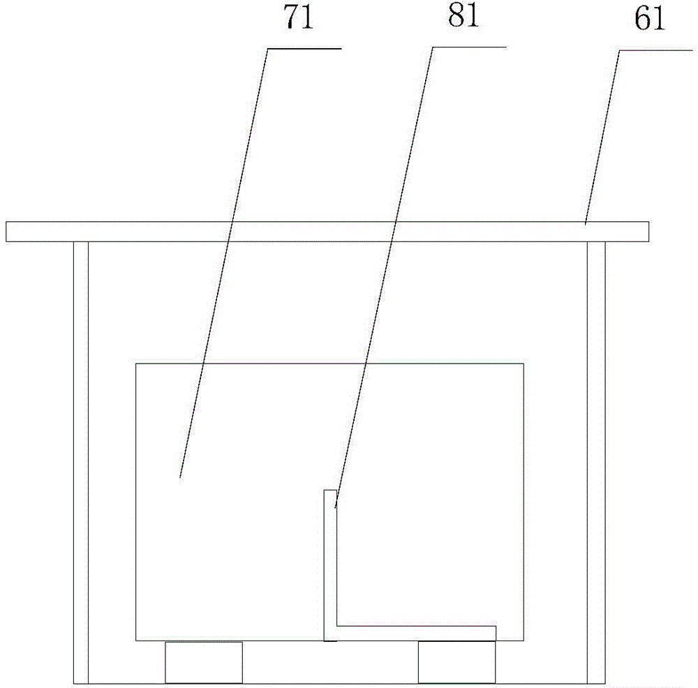
[0026] figure 1 The basic structural diagram of the cabinet-type transformer in Embodiment 1 of the present invention is schematically given, as figure 1 As shown, the cabinet transformer includes:

[0027] Cabinet body 61, described cabinet body comprises cabinet door, top, side and base;

[0028] "L" shaped part 81, said "L" shaped part is made of triangular steel, including horizontal section and vertical section, wherein the horizontal section is fixed on the base, the top of the vertical section is provided with a through hole, and the bolt passes through Through the through hole, the transformer cable is wound on the bolt to fix the cable;

[0029] A transformer body 71, the transformer adopts a dry-type transformer and is fixed on the base;

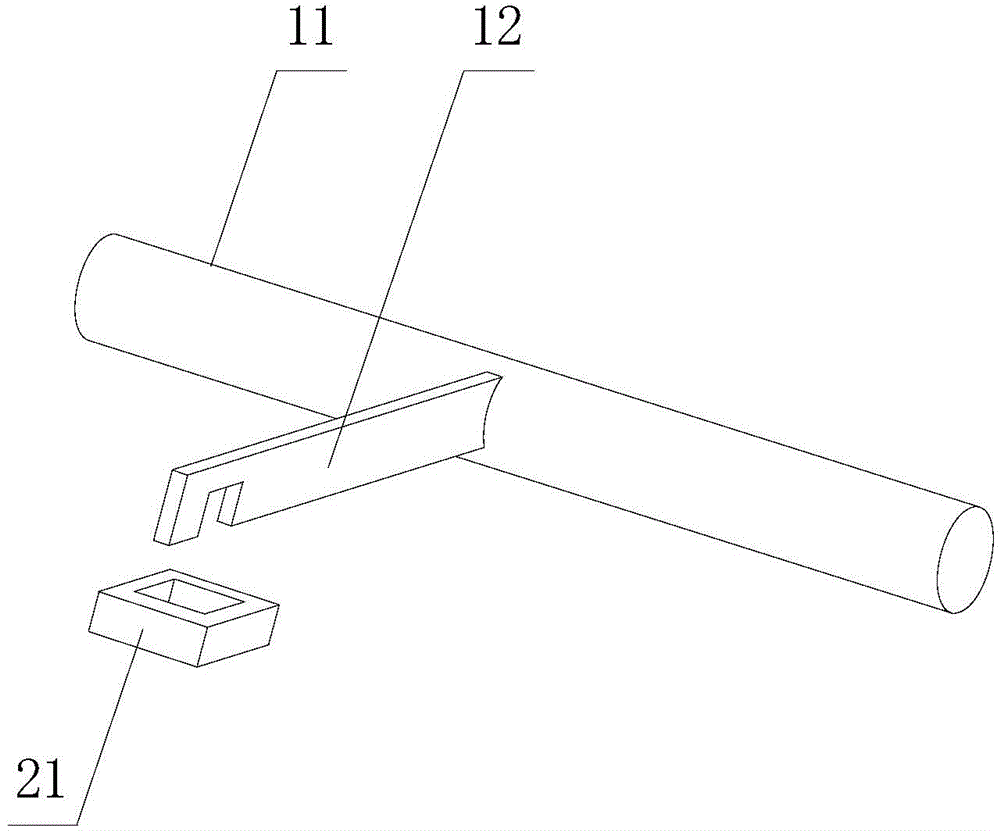
[0030] figure 2 Schematically provides the basic structural diagram of the cabinet lock of Embodiment 2 of the present invention, as figure 2 As shown, the cabinet lock includes:

[0031] The rotating part 11, the rotating ...


PUM


Abstract

The invention provides a cabinet type transformer. The cabinet type transformer comprises a cabinet, a cabinet door, a transformer body and an L-shaped component. The transformer body is installed on a base of the cabinet, the L-shaped component comprises a horizontal section and a vertical section, the horizontal section is fixed to the base, the vertical section is provided with a through hole, and a bolt penetrates through the through hole. The cabinet type transformer has the advantages of being long in service life, safe and the like.

Description

technical field [0001] The invention relates to transformers, in particular to cabinet-type transformers. Background technique [0002] Power transformers are one of the main equipment in power plants and substations. The role of the transformer is multifaceted. It can not only increase the voltage to send electric energy to the power consumption area, but also reduce the voltage to the voltage used at all levels to meet the needs of power consumption. Transformers are usually placed in the open air without protection measures, and have disadvantages, such as: [0003] 1. The transformer is placed in the open air. After all year round and wind and rain, especially after acid rain corrosion, the surface components will be corroded, which reduces the service life; [0004] 2. The protection ability is poor, and criminals can easily pick the lock and illegally invade and destroy it. Contents of the invention [0005] In order to solve the above-mentioned deficiencies in th...

Claims


Application Information

Patent Timeline
Patent Type & Authority Applications(China)
IPC IPC(8): H01F27/00H02B1/26E05C19/08
Inventor 陈明珠刘朝振王建兵
Owner WUHU JINNIU ELECTRIC
Why Eureka
Try Eureka