Waterproof sealing structure of plastic-sealed stator and bearing end cover and plastic-sealed motor
A plastic-encapsulated stator and waterproof sealing technology, which is applied to electrical components, electromechanical devices, electric components, etc., can solve problems such as poor waterproof and sealing effects, and achieve the effects of facilitating installation, improving waterproof and sealing effects, and ensuring stability and reliability
- Summary
- Abstract
- Description
- Claims
- Application Information
AI Technical Summary
Problems solved by technology
Method used
Image
Examples
Embodiment 1
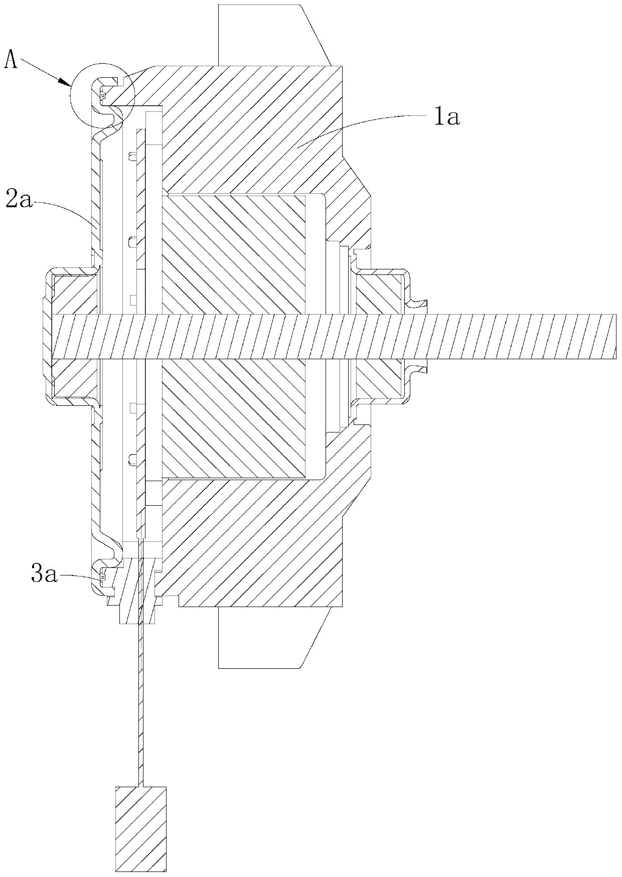
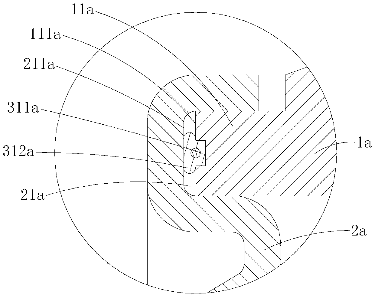
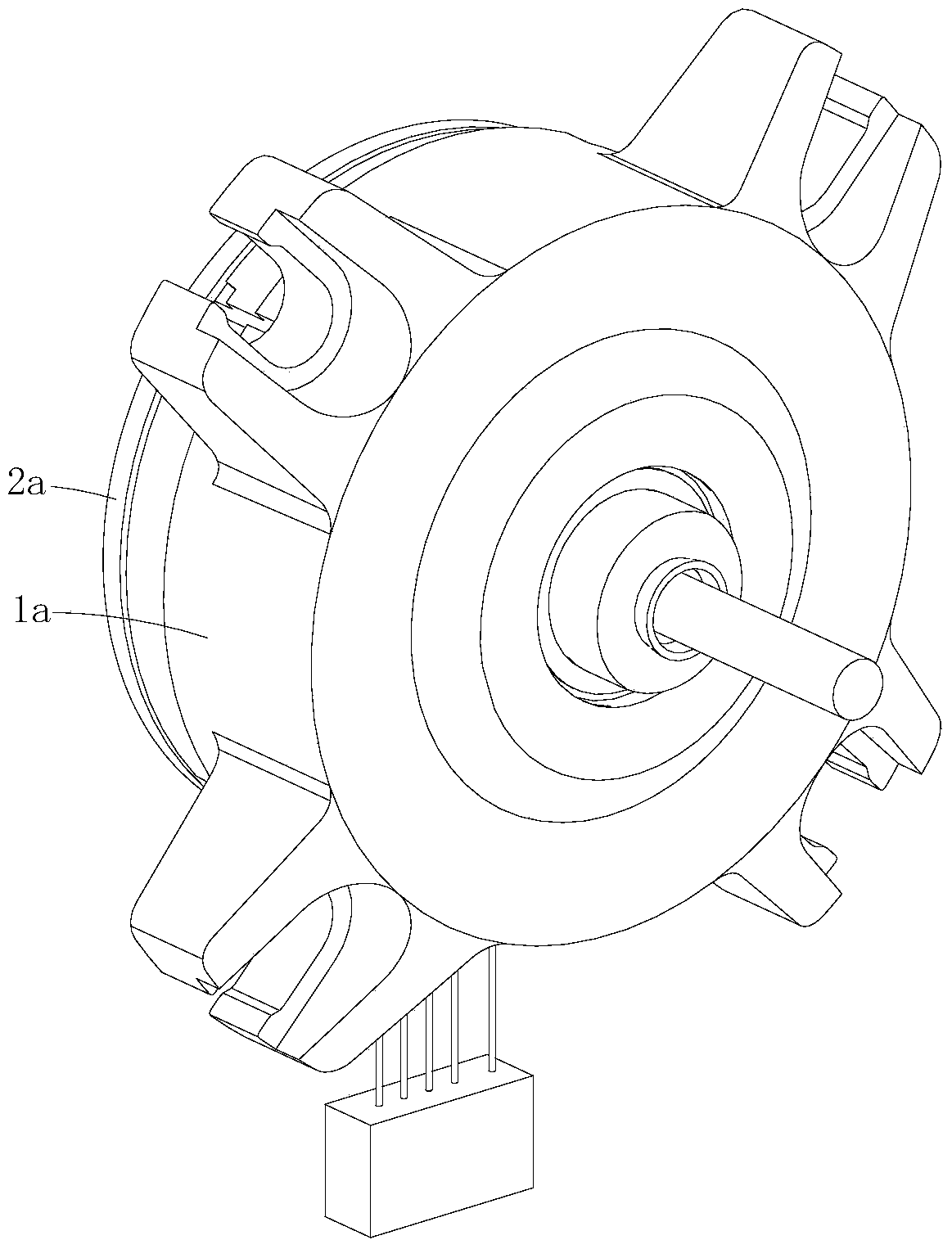
[0041] Such as Figure 1-12 As shown, the waterproof sealing structure of the plastic-encapsulated stator and the bearing end cover provided by the first embodiment of the present invention includes the plastic-enclosed stator 1a and the bearing end cover 2a arranged at the outer end of the plastic-enclosed stator 1a, and the plastic-enclosed stator 1a is provided with an annular locking protrusion. edge 11a, the bearing end cover 2a is provided with an annular slot 21a that fits with the annular locking flange 11a, and the annular locking flange 11a has an axis facing the bearing end cover 2a along the axial direction of the plastic-sealed stator 1a. Towards the end face 111a, the radially inner surface 113a facing the central axis of the plastic-encapsulated stator 1a along the radial direction of the plastic-enclosed stator 1a, and the radially outer surface 112a facing away from the central axis of the plastic-enclosed stator 1a along the radial direction of the plastic-enclo...
Embodiment 2
[0052] Such as Figures 13 to 16 As shown, in the waterproof sealing structure of the plastic-sealed stator and bearing end cover provided in this embodiment and the plastic-sealed motor, the positioning groove is at least one local groove 110b provided at a local circumferential position of the ring-shaped locking flange 11b, and the waterproof seal The ring 3b includes an annular sealing body 31b and protruding parts 32b protruding from one side of the annular sealing body 31b and having the same number as the local grooves 110b, and each protruding part 32b is inserted into each local groove 110b . After the bearing cover and the waterproof sealing ring 3b are installed on the plastic-sealed stator 1b, the annular sealing body 31b is elastically compressed between the axial end surface 111b of the annular locking flange 11b and the bottom groove surface of the annular locking groove. The main difference between this embodiment and the first embodiment lies in the structura...
Embodiment 3
[0061] Such as Figure 17 and Figure 18 As shown, the same as the second embodiment, in the waterproof sealing structure of the plastic-sealed stator and the bearing end cover provided by this embodiment, the positioning groove is also at least one local part located at a local circumferential position of the ring-shaped locking flange 11c. The groove 110c, correspondingly, the waterproof sealing ring 3c also includes an annular sealing body 31c and protrusions 32c protruding from one side of the annular sealing body 31c and having the same number as the local grooves 110c, and each protrusion 32c They are inserted and positioned in the local grooves 110c respectively. After the bearing cover and the waterproof sealing ring 3c are installed on the plastic-sealed stator 1c, the annular sealing body 31c is elastically compressed on the axial end surface 111c of the annular locking flange 11c and the ring between the bottom groove surfaces of the grooves; and the difference fro...
PUM
 Abstract
Description
Claims
Application Information
 - R&D
- Intellectual Property
- Life Sciences
- Materials
- Tech Scout
- Unparalleled Data Quality
- Higher Quality Content
- 60% Fewer Hallucinations
Browse by: Latest US Patents, China's latest patents, Technical Efficacy Thesaurus, Application Domain, Technology Topic, Popular Technical Reports.
© 2025 PatSnap. All rights reserved.Legal|Privacy policy|Modern Slavery Act Transparency Statement|Sitemap|About US| Contact US: help@patsnap.com


