Communication method based on PLC, device and PLC networking system

A communication method and equipment technology, applied in the field of communication, can solve problems such as communication failure between the sending end and the receiving end

Active Publication Date: 2015-04-22
HUAWEI DIGITAL POWER TECH CO LTD
View PDF4 Cites 7 Cited by
  • Summary
  • Abstract
  • Description
  • Claims
  • Application Information

AI Technical Summary

Problems solved by technology

example, such as figure 1 As shown, if the power lines A and C cross during the construction process, the receiving end mistakenly regards the power line C as A to receive the modulated signal transmitted by the transmitting end. Since the

Method used


Image

  • Communication method based on PLC, device and PLC networking system
  • Communication method based on PLC, device and PLC networking system
  • Communication method based on PLC, device and PLC networking system

Examples


Embodiment 1

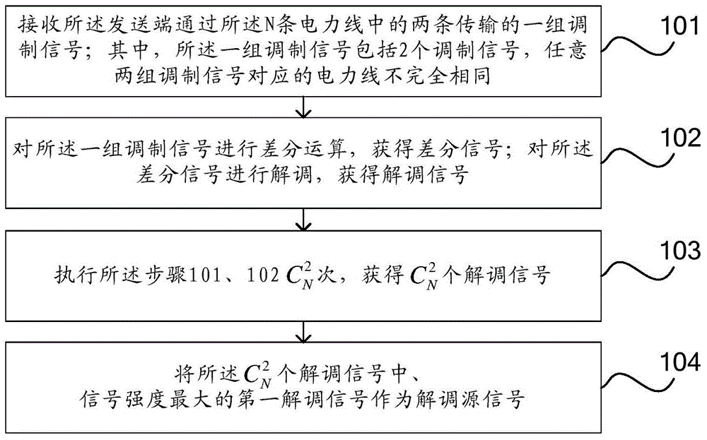
[0059] The embodiment of the present invention provides a PLC-based communication method, the execution subject is the receiving end, such as figure 2 As shown, the method includes the following steps:

[0060] 101. Receive a set of modulated signals transmitted by the sending end through two of the N power lines; wherein the set of modulated signals includes two modulated signals, and any two sets of modulated signals correspond to different power lines.

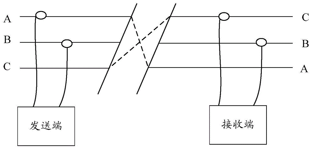
[0061] It should be noted that N power lines are arranged between the receiving end and the sending end, and the sending end sends N modulation signals to the receiving end through the N power lines, and each power line transmits a modulation signal, so The N modulation signals are obtained by the sending end according to the same source signal, and the phase of each modulation signal is the same as the phase of the AC current on the power line transmitting the modulation signal, and the N is an integer greater than or equ...

Embodiment 2

[0085] The embodiment of the present invention provides a device 30, which is deployed at the receiving end, such as Figure 5 As shown, the device 30 includes: a switching control unit 301 and a signal demodulation unit 302 .

[0086]It should be noted that N power lines are arranged between the receiving end and the sending end, and the sending end sends N modulation signals to the receiving end through the N power lines, and each power line transmits a modulation signal, so The N modulation signals are obtained by the sending end according to the same source signal, and the phase of each modulation signal is the same as the phase of the AC current on the power line transmitting the modulation signal, and the N is an integer greater than or equal to 3.

[0087] The switching control unit 301 is configured to receive a set of modulation signals transmitted by the transmitting end through two of the N power lines; wherein, the set of modulation signals includes 2 modulation si...

Embodiment 3

[0102] The embodiment of the present invention provides a device 40, which is deployed at the sending end, such as Figure 7 As shown, the device 40 includes: a signal modulation unit 401 .

[0103] It should be noted that N power lines are provided between the sending end and the receiving end, and the N is an integer greater than or equal to 3.

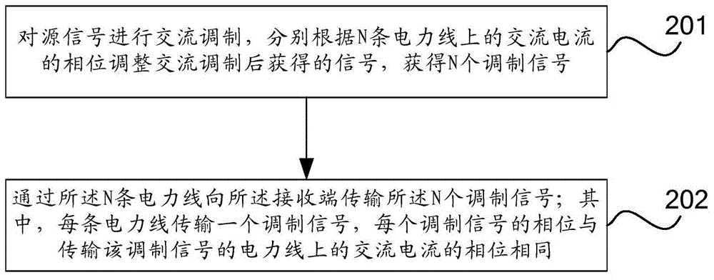
[0104] The signal modulation unit 401 is configured to perform AC modulation on the source signal; respectively adjust the signals obtained after AC modulation according to the phases of the AC currents on the N power lines to obtain N modulated signals; send the signal to the receiving end through the N power lines The N modulation signals are transmitted; wherein, each power line transmits a modulation signal, and the phase of each modulation signal is the same as the phase of the alternating current on the power line transmitting the modulation signal.

[0105] The device provided by the embodiment of the present invention perfo...


PUM


Abstract

The embodiment of the invention provides a communication method based on a PLC, a device and a PLC networking system and relates to the field of communication. Alternating current power lines led out of an inverter do not need to be distinguished during communication, engineering installation is easy and convenient, and transmission reliability is high. The communication method comprises the steps that firstly, a set of modulating signals transmitted by a sending end via two of the N power lines are received, wherein the modulating signal set comprises two modulating signals, and the power lines corresponding to any two modulating signal sets are not identical; secondly, difference operation is carried out on one modulating signal set, a differential signal is obtained and demodulated, and a demodulating signal is obtained; the first step and the second step are executed for many times shown in the specification, and demodulating signals with the number shown in the specification are obtained; the first demodulating signal with the maximal signal strength in the demodulating signals serves as a demodulating source signal.

Description

technical field [0001] The present invention relates to the communication field, in particular to a communication method, equipment and PLC networking system based on PLC (Power Line Communication, power line communication). Background technique [0002] PLC technology, that is, the transmitting end performs AC modulation on the source signal to be transmitted to obtain the modulated signal, and sends the modulated signal to the receiving end through the AC cable (that is, the wire output by the inverter), and the receiving end receives the modulated signal, and the modulated signal Demodulate to obtain the source signal. [0003] Typically, the inverter outputs three AC power lines. Such as figure 1 As shown, it is a schematic diagram of the existing PLC communication system. The source signal to be sent is modulated at the sending end, and the modulated signal is transmitted to the receiving end through A and B of the three power lines. Receive two modulated signals. A...

Claims


Application Information

Patent Timeline
IPC IPC(8): H04B3/54
Inventor 赵小亮水伟
Owner HUAWEI DIGITAL POWER TECH CO LTD
Why Eureka
Try Eureka