Demosaicing method and device of image sensor

An image sensor and demosaic technology, applied in image enhancement, image data processing, picture signal generator and other directions, can solve the problems of bright color aliasing and low resolution, and achieve the effect of weakening artificial traces and suppressing the phenomenon of bright color aliasing.

Active Publication Date: 2015-04-22
SHANGHAI FULLHAN MICROELECTRONICS
View PDF5 Cites 22 Cited by
  • Summary
  • Abstract
  • Description
  • Claims
  • Application Information

AI Technical Summary

Problems solved by technology

However, this method of independently interpolating each channel does not use the information between channels a...

Method used


Image

  • Demosaicing method and device of image sensor
  • Demosaicing method and device of image sensor
  • Demosaicing method and device of image sensor

Examples


Embodiment 1

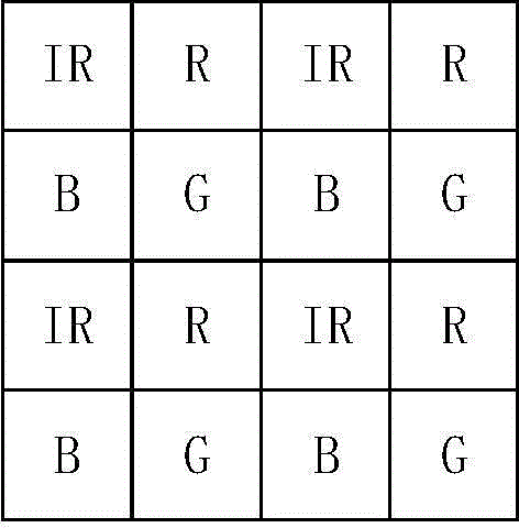
[0089] Embodiment 1 (the following embodiments all take the RGBIR image sensor as an example)

[0090] Figure 6 The flow chart of the first embodiment of the demosaicing method provided by the present invention specifically includes the following steps:

[0091] S6.1, the pre-processing unit obtains the correction factor θ of the infrared channel. The correction factor is multiplied by the original infrared channel pixel value IR to obtain the corrected infrared channel pixel IR'. For the specific calculation method of the correction factor, please refer to the follow-up Figure 9 and corresponding instructions.

[0092] S6.2, the demosaicing unit obtains the preset 5×5 neighborhood luminance L interpolation parameters, and the RAW signal of the current pixel 5x5 neighborhood is convoluted to obtain the luminance signal P of the current pixel position L , the 5×5 neighborhood is taken as an example here, but it is not limited thereto.

[0093] S6.3, the demosaic unit obt...

Embodiment 2

[0099] Figure 7 The flow chart of the second embodiment of the demosaicing method provided by the present invention specifically includes the following steps:

[0100] S7.1, the pre-processing unit obtains the correction factor θ of the infrared channel. The correction factor is multiplied by the original infrared channel pixel value IR to obtain the corrected infrared channel pixel IR'.

[0101] S7.2, the demosaicing unit obtains the preset chroma C1 interpolation parameters of the 5×5 neighborhood, and obtains the chroma C1 signal at the current pixel position through convolution operation with the RAW signal of the 5×5 neighborhood of the current pixel .

[0102] S7.3, the demosaic unit obtains the preset 5×5 neighborhood chroma C2 interpolation parameters, and obtains the chroma C2 signal at the current pixel position through convolution operation with the RAW signal of the current pixel 5×5 neighborhood .

[0103] S7.4, the demosaic unit obtains the preset 5×5 neig...

Embodiment 3

[0108] Figure 8 It is a flow chart of another embodiment of the demosaicing method provided by the present invention, specifically including the following steps:

[0109] S8.1, the statistical unit calculates the infrared correction factor, and corrects the infrared channel.

[0110] S8.2, calculate the local gradient values ​​of the four channels in the horizontal (H), vertical (V) and diagonal (D1, D2) directions in the 5×5 neighborhood centered on the current pixel. details as follows:

[0111] ▽Hg=(abs(G 24 -G 22 )+abs(G 44 -G 42 )) / 2

[0112] ▽Vg=(abs(G 22 -G 42 )+abs(G 24 -G 44 )) / 2

[0113] ▽D1g=abs(G 22 -G 44 )

[0114] ▽D2g=abs(G 24 -G 42 )

[0115]▽Hr=(abs(R 12 -R 14 )+abs(R 32 -R 34 )+abs(R 52 -R 54 )) / 3

[0116] ▽Vr=(abs(R 12 -R 32 )+abs(R 32 -R 52 )

[0117] +abs(R 14 -R 34 )+abs(R 34 -R 54 )) / 4

[0118] ▽D1r=(abs(R 12 -R 34 )+abs(R 32 -R 54 )) / 2

[0119] ▽D2r=(abs(R 14 -R 32 )+abs(R 34 -R 52 )) / 2

[0120] ▽Hir=(abs(IR ...


PUM


Abstract

The invention discloses a demosaicing method and device of an image sensor. The method includes the steps that 2*2 serves as shortest sampling cycles, an original RAW image obtained through the image sensor with four different filters exists in each shortest sampling cycle is taken as an output result formed after original color gamut images of four full breadths are added through a sampling function; the conversion relations between brightness, chrominance components and the original color gamuts corresponding to the four filters of the image sensor are defined, and each RAW image is taken as an output result generated after adding brightness and the chrominance components of the four full breadths through the sampling function; demosaicing computation is carried out on the brightness and the three chrominance components, and a brightness and chrominance signal of a current pixel position is restored from input RAW data; a corresponding original color gamut image signal is obtained by converting the brightness and chrominance signal of the current pixel position through matrix operation after demosaicing. The method and device can solve the problems that the resolution ratio of output images after demosaicing is low and bright color aliasing is severe.

Description

technical field [0001] The present invention relates to the field of image signal processing, in particular to a demosaicing method and device based on an image sensor with 2×2 minimum sampling period and four different filters in each minimum sampling period. Background technique [0002] The image sensor in the Bayer format only samples one of the three primary colors of red, green and blue at each pixel position. In order to improve the resolution of the output image after demosaicing, the Bayer format image sensor samples green at the diagonal position of its minimum sampling period of 2×2. [0003] Some applications require imaging devices to provide RGB images and infrared images of the scene at the same time. From the perspective of cost reduction, this requires the image sensor to collect infrared light while sampling the three primary colors of red, green and blue. The simplest improvement method based on the existing Bayer format sensor is to replace a green filte...

Claims


Application Information

Patent Timeline
IPC IPC(8): H04N9/04G06T5/00
Inventor 董鹏宇田景军党韩兵陈晓春李源章旭东
Owner SHANGHAI FULLHAN MICROELECTRONICS
Why Eureka
Try Eureka