
Electro-optic displays, and method for driving same

Active Publication Date: 2005-07-14
E INK CORPORATION
View PDF99 Cites 87 Cited by
  • Summary
  • Abstract
  • Description
  • Claims
  • Application Information

AI Technical Summary

Benefits of technology

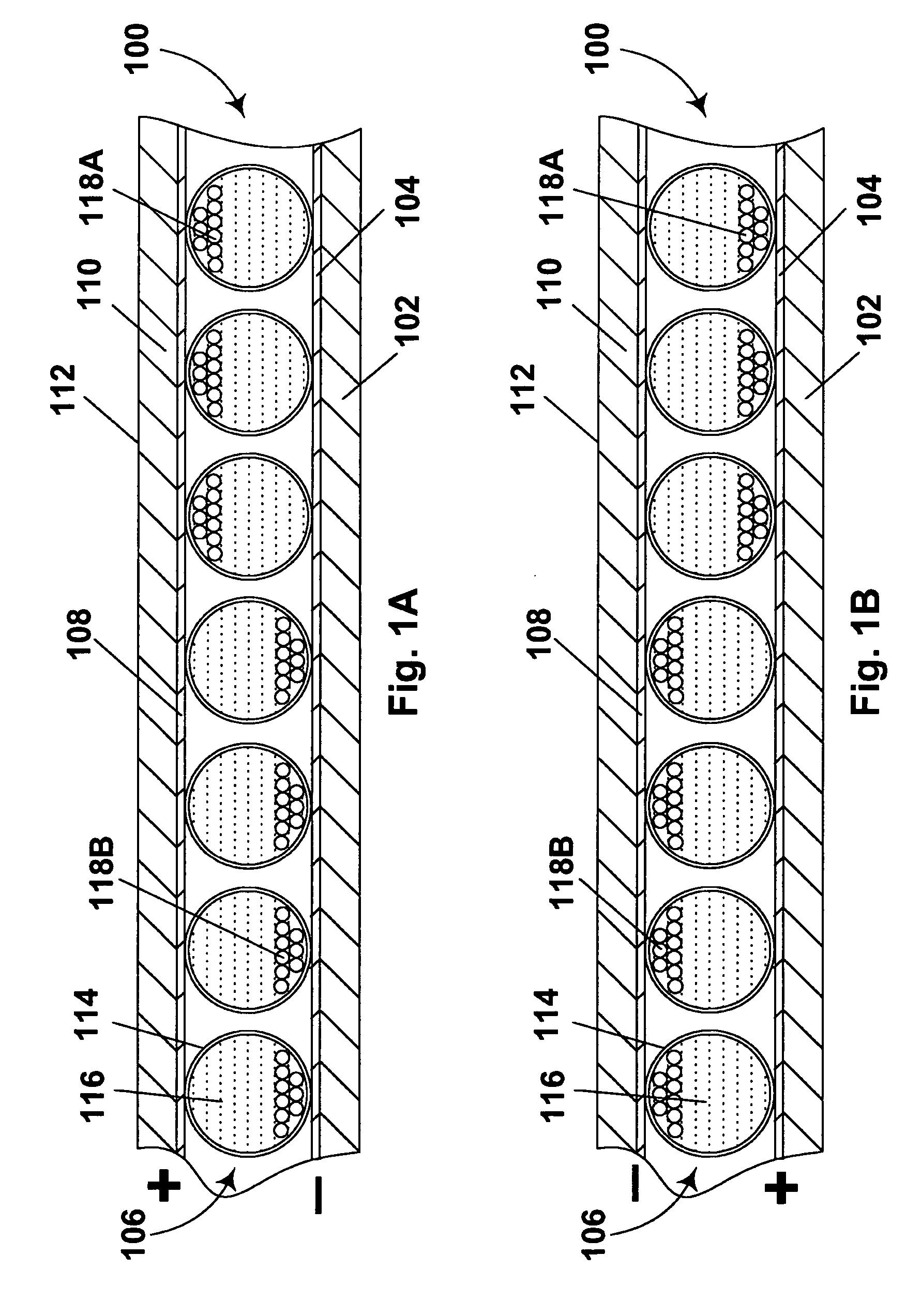
[0044] applying an electric field in said opposed direction across the layer of electro-optic medium, thereby causing the at least one first area to display said second optical characteristic and said at least one second area to display said fourth optical characteristic.
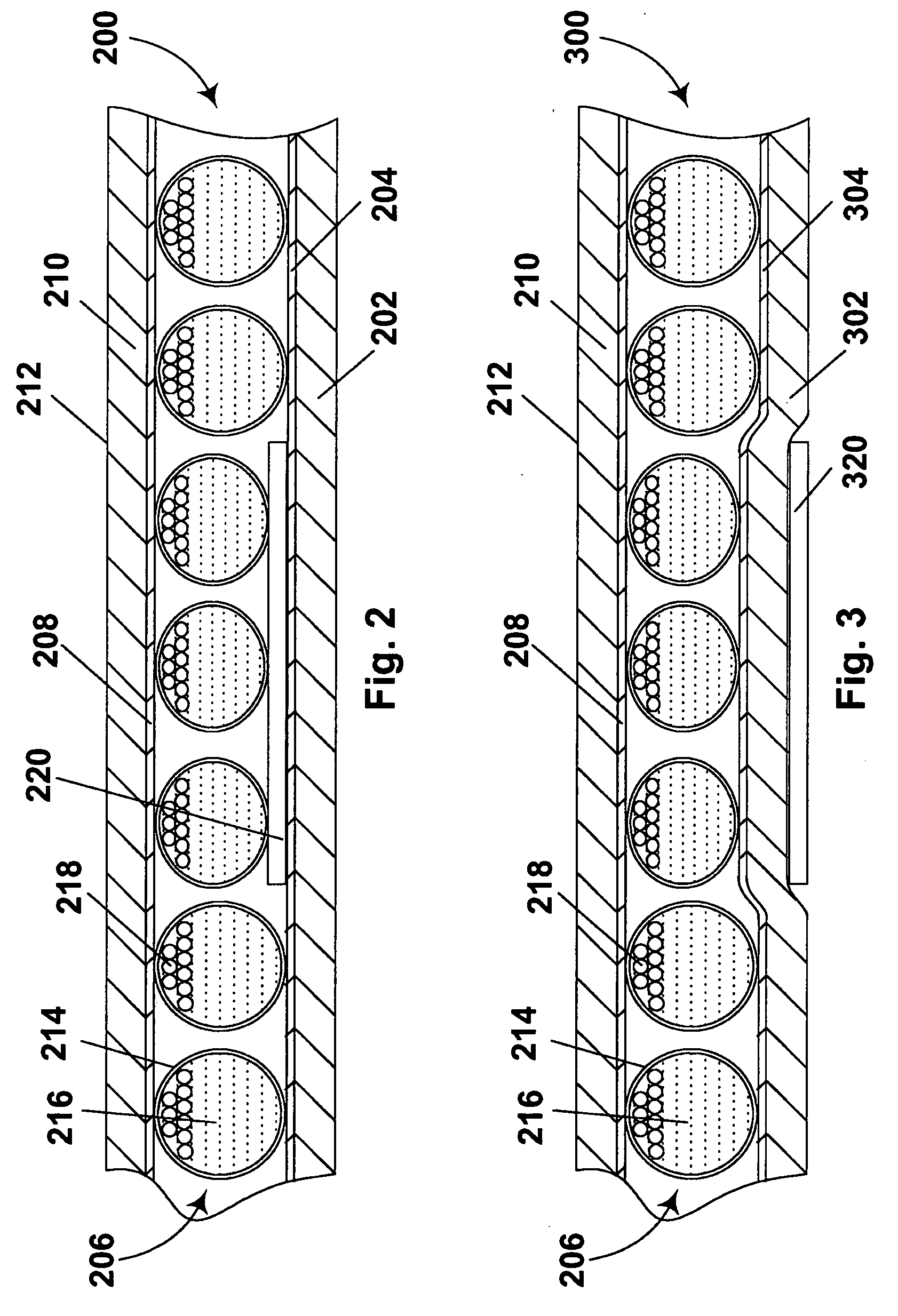
[0049] The invention also provides a convenient and economical process for producing an internal shim differential thickness display. In this process, a layer of conductive material (typically a thin metal film supported on a substrate) is imagewise printed with an ink, and the ink-bearing conductive layer is thereafter fixed adjacent (typically laminated to) an electro-optic layer to form the final display. Conveniently, the ink-bearing conductive layer is laminated to a front plane laminate as described in the aforementioned 2004 / 0027327. Many commercial inks, typically those containing substantial amounts of polymer, give dried ink layers suitable for use as internal shims in the present displays, and since printing technologies capable of printing on metal foils are well developed, being used commercially on a large scale to prepare decorative wrapping materials, such printing processes provide an economical way to prepare backplanes for use in the displays of the present invention.

Problems solved by technology

Nevertheless, problems with the long-term image quality of these displays have prevented their widespread usage.
For example, particles that make up electrophoretic displays tend to settle, resulting in inadequate service-life for these displays.
Such gas-based electrophoretic media appear to be susceptible to the same types of problems due to particle settling as liquid-based electrophoretic media, when the media are used in an orientation which permits such settling, for example in a sign where the medium is disposed in a vertical plane.
Indeed, particle settling appears to be a more serious problem in gas-based electrophoretic media than in liquid-based ones, since the lower viscosity of gaseous suspending fluids as compared with liquid ones allows more rapid settling of the electrophoretic particles.
However, the cost reductions provided by the use of encapsulated electrophoretic media have hitherto not been accompanied by corresponding cost reductions in the components used for driving the display.
Although such active matrix backplanes can write any desired image on the electro-optic medium, they are expensive, the cost of the backplane amounting to about 80 per cent of the total cost of the display.
Furthermore, since such backplanes are typically produced using semiconductor fabrication techniques developed for use in the computer industry, the maximum size of the individual backplanes is limited, and large displays, for example those used to display data in airports, or railroad stations, or as billboards, may require the use of the multiple backplanes “tiled” to cover the desired area; such tiling produces additional complications, such as providing robust leads to ensure that the necessary data are supplied to each individual display.
It will readily be apparent that displays intended to display large numbers of characters will require very large numbers of electrodes, and that the cost of fabricating such large numbers of electrodes, together with the voltage supply lines and control circuits necessary to drive the electrodes, results in substantial costs for the direct drive backplane.
One of the problems with many electro-optic displays is the limited range of colors which each pixel of the display can produce.
For example, a display having black and white extreme optical states may be capable of displaying multiple shades of gray, but is not capable of displaying any colors other than black, white and gray.
However, for the reasons already discussed, the available color gamut from such a display is inherently limited.
The main problem with this approach to generating color is that the brightness of the display is limited by the pixelation of the color filter.
For example, if a red color is desired, the pixels covered by red filters are set to appear red, whereas the pixels covered by green and blue filters are set to appear dark, so that only a fraction of the display surface has the desired color while the remaining portion is dark, thus limiting the brightness of any color obtained.
However, this approach suffers from limited brightness similar to that of the color filter approach, in that, for example, if a red area is desired only a fraction of the desired area can be set to appear red.
Both the color filter and patterned media approaches require registration of the differing areas of the filter or media with multiple sets of electrodes, and may involve complex techniques for producing the display, thus increasing the cost of the display and possibly compromising its optical quality, especially in the case of high resolution displays in which the individual pixels are very small.

Method used


Image

  • Electro-optic displays, and method for driving same
  • Electro-optic displays, and method for driving same
  • Electro-optic displays, and method for driving same

Examples


example

[0090] The mixed color display described in this Example used two different types of opposite charge dual particle encapsulated electrophoretic media, with all four types of electrophoretic particles polymer-coated by the type of processes described in the aforementioned U.S. Pat. No. 6,822,782 (which require surface functionalization of the raw pigment surface before formation of the polymer). Accordingly, the procedures for functionalization and polymer formation will be described before the procedures for forming the capsules and the final display.

[0091] Surface Functionalization A: Positively Charged Pigments

[0092] A 1 L Erlenmeyer flask equipped for rapid magnetic stirring was charged with 600 mL of ethanol, 60 mL of deionized water, and 7.2 mL of ammonium hydroxide. 3-(N-styrylmethyl-2-aminoethylamino)propyltrimethoxysilane (53 mL of a 40% solution in methanol, UCT) was added to the resultant mixture and allowed to stir for five minutes. Raw pigment (60 g) was added to the m...


PUM


Abstract

Electro-optic media are disclosed containing a plurality of types of electro-optic media within a single layer. The media provide blinking displays, displays in which images appear transiently and displays having a wider color gamut than conventional electro-optic displays

Description

REFERENCE TO RELATED APPLICATIONS [0001] This application claims benefit of Application Ser. No. 60 / 481,847, filed Dec. 31, 2003, and of Application Ser. No. 60 / 561,754, filed Apr. 13, 2004. [0002] The entire contents of the aforementioned applications are herein incorporated by reference. The entire contents of all United States Patents and published and copending Applications mentioned below are also herein incorporated by reference.BACKGROUND OF THE INVENTION [0003] This invention relates to electro-optic displays and to methods for driving such displays. More specifically, in one aspect this invention relates to electro-optic displays with simplified backplanes, and methods for driving such displays. In another aspect, this invention relates to electro-optic displays in which multiple types of electro-optic units are used to improve the colors available from the displays. The present invention is especially, though not exclusively, intended for use in electrophoretic displays. [...

Claims


Application Information

Patent Timeline
IPC IPC(8): G02B26/00G02F1/167G02F1/16755
CPCG02F1/167G02F1/16755
Inventor HONEYMAN, CHARLES HOWIEPAOLINI, RICHARD J. JR.STEINER, MICHAEL L.WHITESIDES, THOMAS H.OLESON, ANDREW Y.
Owner E INK CORPORATION
Learn More